Radio Shield
Contents
[hide]Description
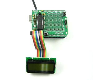
The Radio Shield is an add-on kit for the Arduino development board that provides AX.25 packet radio send and receive capability, a prototyping area, and an HD44780-compatible LCD interface.
Packets are sent and received in AX.25 UI frames at 1200 baud. This allows operation on the VHF APRS network.
Radio Shield 2
The Radio Shield 2 replaces the original Radio Shield and comes pre-assembled, except for the pin headers that connect it to the Arduino. The interface is unchanged. Further documentation will be posted soon.
Assembly
Parts list:
| Part Number | Value | Notes |
|---|---|---|
| R1,R5,R10 | 10k | brown-black-orange |
| R4 | 10m | brown-black-blue |
| R3,R12,R13 | 680 | blue-gray-brown |
| R7 | 6.8k | blue-gray-red |
| R9 | 240k | red-yellow-yellow |
| R6 | 2.2k | red-red-red (optional, for HT PTT mode) |
| R2 | 2.2k | red-red-red |
| Q1 | 2N7000 | |
| Y1 | 29.4912 MHz crystal | |
| C4,C5 | 18pF | |
| C1,C3,C6 | 0.1uF | |
| C2 | 10uF | negative lead toward C2 marking |
| D14 | Red/Green LED | Install with longest lead toward board edge |
Construction:
- Check parts list to ensure you have all necessary parts.
- Locate part locations on PCB next to their silk screen labels.
- Begin by inserting lowest profile parts and soldering into place first, working up to the taller pieces.
- Install parts in the following order easiest construction:
- Resistors (R1-7, R9-13) - R6 is *not* needed for Kenwood and Chinese import radios, do not install if it is not needed!
- Capacitors (C1, C3-6) - not C2 yet
- Crystal (Y1) - be sure to fold crystal over as seen in photo.
- IC socket - don't install the IC yet
- Push button (P1)
- LED - longest lead toward board edge
- Taller Capcitor (C2)
- Transistor (Q1) - note the orientation on the silk screen
- Component side pin headers (be sure to remove jumpers under after soldering)
- Arduino side pin headers
- Insert U3 into socket
- Solder on data cable paying attention to the pinout for your particular radio
- Program Arduino with sample code from below, connect radio and insert shield to Arduino. Ensure that jumpers are on RUN side of pin header.
Radio Interfacing
Four interface lines are provided at one edge of the board for connecting a radio:
| Pin | Function |
|---|---|
| GND | Ground |
| TX | Transmit audio (radio mic) |
| RX | Receive audio (radio speaker) |
| PTT | Push-to-talk (active low) |
For hand-held radios that don't have a separate PTT line (most makes and models except for Kenwoods and Chinese imports) install the provided 2.2k resistor (red-red-red color code) in position R6.
Usage
Keep both JP7 jumpers in RUN position for communication with Arduino. Use PROG position for serial pass-through to shield. Remove jumpers (or the entire shield) when programming the Arduino board.
All serial communication with the Radio Shield is at 4800 baud. Use Serial.begin(4800); to achieve this.
Configuration parameters are stored in flash memory, therefore only need to be called once. ( i.e. in setup() )
All commands start with a single character and end with a CR/LF.
LCD Commands
| Command | LCD Function |
|---|---|
| W<text> | Write to LCD |
| G<line,column> | Go to LCD line (0 or 1) and column |
| C | LCD clear |
| H | LCD home |
| B<n> | LCD contrast, 0-1023 |
Note that pin 16 of the LCD interface does not connect to any other circuitry on the PCB. Some LCD panels may require this pin to be connected to ground. If your display's backlight does not turn on when power is supplied to the Arduino and RadioShield, you may need to ground this pin - check your LCD's datasheet to be sure.
Radio Commands
| Command | Function |
|---|---|
| !<text> | Send plain text packet |
| @<text> | Send Morse code text |
| M<callsign> | Set my callsign (returns 1 for success) |
| S | Status. Returns 1. |
| V | Reports version. Added in firmware version 1.1. |
| L<0-255> | Set TX audio level (returns 1 for success) |
| D<0-255> | Set TX delay in 1/120 sec intervals (returns 1 for success) |
| P<path> | Set AX.25 path (e.g., WIDE1-1,WIDE2-1) |
Received Packet Format
Received packets are output with source and destination call, followed by packet contents and CR/LF, e.g.:
N1VG-14>APOTW1:!3455.15N/12026.29W_301/005g009t067P000h36b10187OTW1
Sample Applications
The following blocks of code are provided as a starting place for your experimentation.
LCD Counter
This code sample displays a counter on the LCD.
int counter = 0;

void setup()                    // run once, when the sketch starts
{
  Serial.begin(4800);
  delay(3);                     // Allow time for RadioShield setup
}

void loop()                     // run over and over again
{
  Serial.print("C\r\n");        // Clear LCD
  delay(10);                     // Clear command takes some time to complete
  Serial.print("WCount");       // Send text to LCD
  Serial.print(counter);
  Serial.print("\r\n");
  delay(8000);                  // Wait a bit
  counter++;
}
Display Incoming Packets
This demo receives incoming packets and displays them to the LCD. Note that there is no line length limiting - displayed packets may wrap strangely depending on the size of your display.
char inbyte = 0;                 // Received byte
char buf[260];                   // Incoming data buffer
int buflen = 0;                  // Length of buffered ata

void setup()                     // Runs at startup
{
  Serial.begin(4800);            // RadioShield runs at 4800 baud
  delay(3);                      // Allow time for RadioShield setup
  Serial.println("B100");        // Set display contrast
  Serial.println("C");           // Clear screen
  delay(10);                     // Can take a bit to clear the LCD, so wait
  Serial.println("WWaiting");    // 'Waiting' message stays until we receive something
}


void loop()                      // Runs constantly after startup
{
  while (Serial.available() > 0) // Check for an incoming byte on the serial port
  {
    inbyte = Serial.read();      // Get the byte
    if (inbyte == '\n')          // Check for end of line
    {
      Serial.println("C");       // Clear screen
      delay(10);                 // Can take a bit to clear the LCD, so wait
      Serial.print("W");
      Serial.println(buf);
      buflen = 0;
    }
    else if (inbyte > 31 && buflen < 260)  // Only record printable characters
    {
      buf[buflen++] = inbyte;
      buf[buflen] = 0;
    }
  }
}
Transmit Packets
This demo will transmit a simple test message about every 30 seconds, with an incrementing counter for each message sent.
int counter = 1;

void setup()
{
  Serial.begin(4800);                      //OPEN SERIAL LINE AT 4800
  delay(3);
  Serial.print("MW1AW\r\n");               //SET YOUR CALLSIGN HERE, HERE YOU SEE W1AW
  delay(10);
  Serial.print("PWIDE1-1,WIDE2-1\r\n");    //SET DIGIPATH HERE
  delay(10);
}

void loop()
{
  Serial.print("!>This is RadioShield test message #");     //BEGIN MESSAGE BUT DON'T SEND YET...
  Serial.print(counter);                                    //  ...CONCATENATE VALUE OF count TO OUTPUT...
  Serial.print("\r\n");                                     //    ...SEND CR/LF TO COMPLETE AND TRANSMIT PACKET.
  counter++;
  delay(30000);                                             //30,000ms = 30sec
}
Note, the delay() is not from the end of the APRS packet, but from the time the transmit command (!...\r\n) was issued. If the APRS transmit takes 1 second to transmit and you are delaying 30sec, the next packet will transmit 29seconds after the previous. This is rarely an issue, just something to keep in mind if you're watching the clock.
Revision History
Firmware revision 1.1 - Released 4/23/2013. Fixed buffer overrun bug in (P)ath command that could cause configuration to become garbled and possibly set permanently to 300 baud mode. Added (V)ersion command.
Useful Links
For more information on creating correctly formed APRS packets, visit the following links:

