OT3m
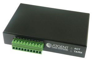
The OT3m is a standalone Tracker3 variant in a steel enclosure, similar to the OT2m that it replaced but with the addition of a USB port and a 10-pin terminal block in place of the OT2m's RJ12 accessory connector.
The main Tracker3 page covers information relevant to all Tracker3 variants. This page contains only information specific to the OT3m model.
Contents
[hide]Connector Pinouts
Male DB9 Serial Connector
| Pin | Function |
|---|---|
| 2 | Data in (port A) |
| 3 | Data out (port A) |
| 4 | Power output for GPS |
| 5 | Ground |
| 7 | Data out (port B) or CTS |
| 8 | Data in (port B) or RTS |
Note: The serial interface is configured as DTE (data terminal equipment) to allow direct connection to a GPS receiver. Connection to a PC requires a nullmodem cable.
Female DB9 RADIO Connector
| Pin | Function |
|---|---|
| 1 | Audio out |
| 2 | COR / Squelch input |
| 3 | PTT out |
| 5 | Audio in |
| 6 | Ground |
| 7 | Power in |
| 8 | PTT in |
Accessory Connector
In place of the modular jack used on the OT1m and OT2m, the OT3m has a 10-position, 0.150" pitch pluggable screw terminal block. Pinouts, from left to right, are as follows:
| Pin | Function |
|---|---|
| 5V | Power output - 5V |
| 1W | Dallas 1-Wire data bus |
| A1 | Analog input 1 |
| A2 | Analog input 2 |
| A3 | Analog input 3 |
| A4 | Analog input 4 |
| CT | Digital counter input |
| IO | Digital I/O |
| PS | Power switch output (7 amps max) |
| GND | Ground |
The analog inputs should not exceed 20 volts, and the digital input should not exceed 5.2 volts.
The IO pin can be used to trigger the 'jumper' option in the profile switching dialog. Grounding the pin corresponds to the jumper 'on' setting, and 5v corresponds to 'off'.
Telemetry
When the telemetry function is enabled, a telemetry packet is sent with the following format:
T#sss,V,A1,A2,A3,A4,JC000000
"sss" is the telemetry sequence number (incremented with each transmission), V is the supply voltage, A1-A4 are the corresponding analog inputs on the accessory connector, J is the status of the digital input marked IO, and C is the configuration profile in use.
All analog values are given in tenths of a volt, e.g. 12.5 volts is shown as 125.
Power Consumption
The OT3m currently draws approximately 50 mA. Future firmware revisions will reduce this as more power saving software functions are implemented.
Keyboard Interface
Starting with PCB version 1.1, the OT3m board has a 6-pin mini-DIN connector that allows connection of a standard PS/2 keyboard. Note that there is no opening in the enclosure for this connector. Presently keyboard input is interpreted the same as input from a serial terminal, so a keyboard can be used to enter commands and send messages without a PC. Keyboard support is currently considered to be an experimental feature.

