File list
From ArgentWiki
This special page shows all uploaded files.
First page |
Previous page |
Next page |
Last page |
| Date | Name | Thumbnail | Size | User | Description | Versions |
|---|---|---|---|---|---|---|
| 11:06, 19 December 2009 | Ws1-side.jpg (file) |  |
365 KB | ScottN1VG | ADS-WS1 Mast | 1 |
| 18:59, 26 September 2011 | Voltage divider.jpg (file) |  |
70 KB | VE6SRV | Added resistors to create a second voltage divider. | 1 |
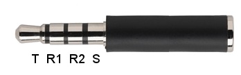
| 11:31, 1 July 2013 | Trrs-plug.jpg (file) |  |
8 KB | ScottN1VG | Tip-ring-ring-sleeve 3.5mm plug | 1 |
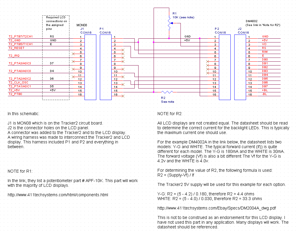
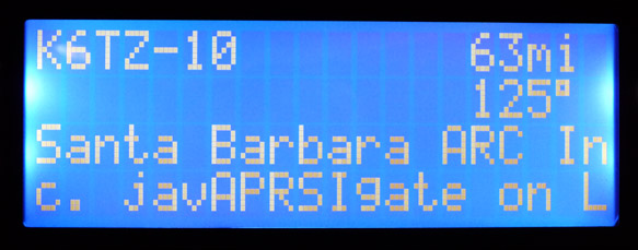
| 10:43, 18 September 2009 | Tracker2-to-LCD-Display.png (file) |  |
30 KB | N7FMH | 1 | |
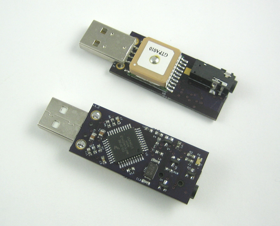
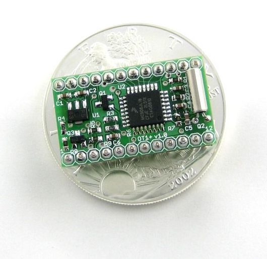
| 11:33, 1 July 2013 | T3-micro.jpg (file) |  |
125 KB | ScottN1VG | 1 | |
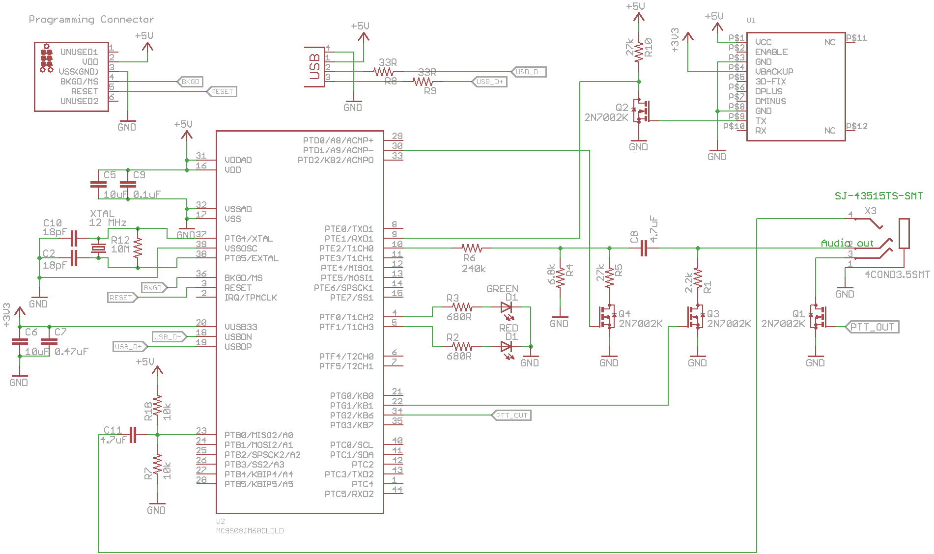
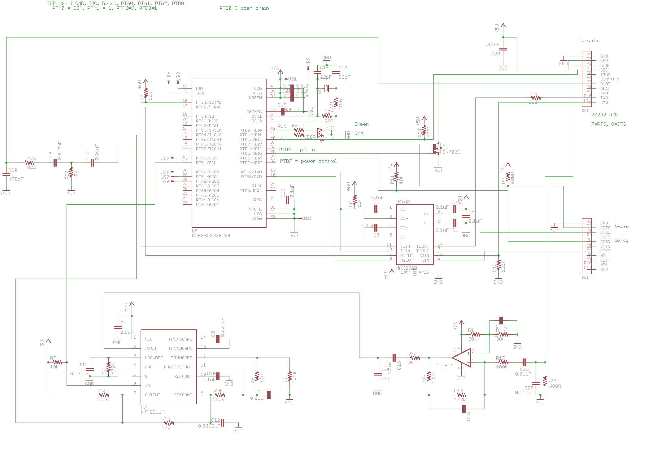
| 17:31, 4 July 2013 | T3-Micro.png (file) |  |
52 KB | ScottN1VG | T3-Micro schematic | 1 |
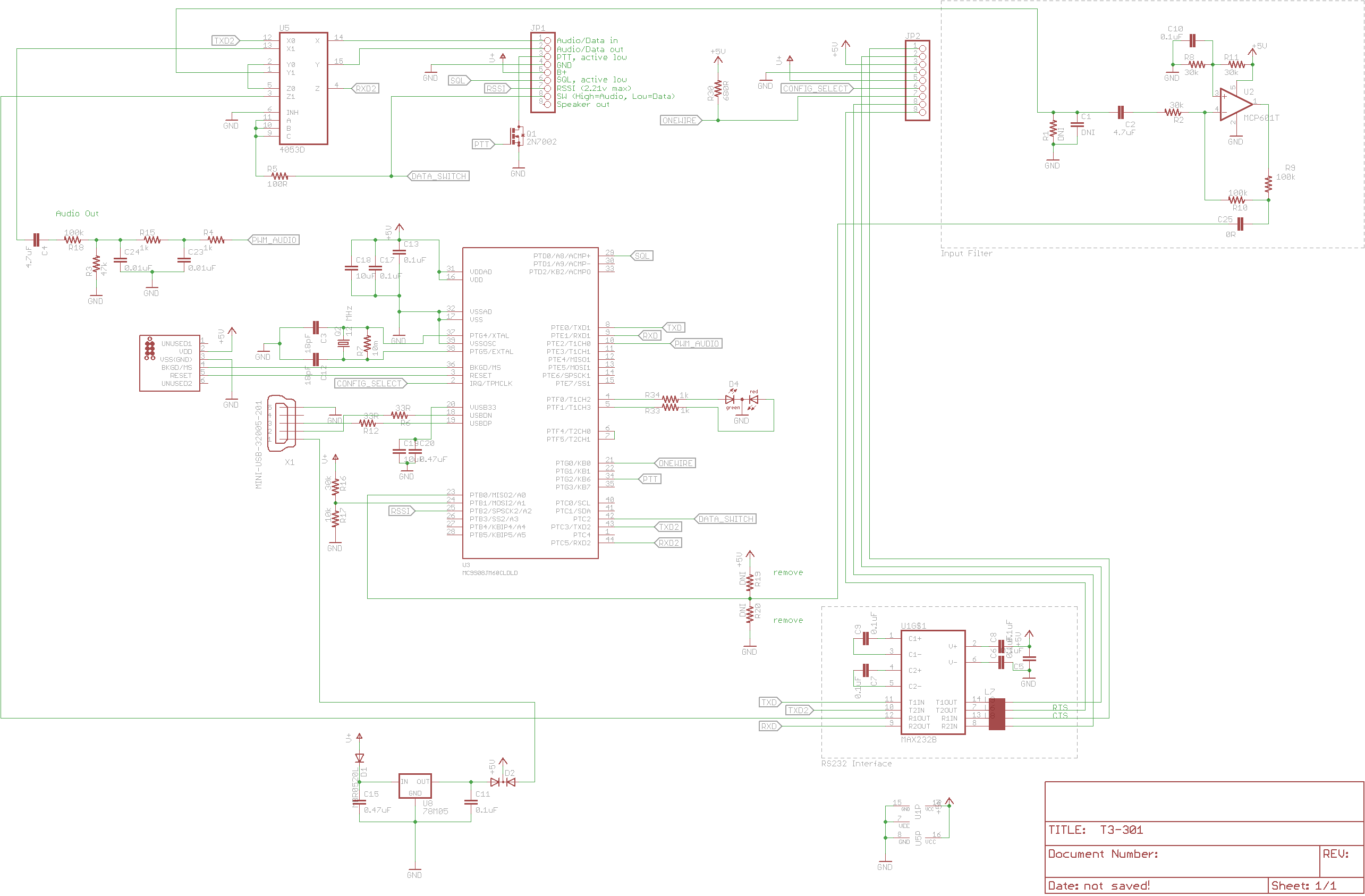
| 00:07, 16 November 2012 | T3-301 Schematic.png (file) |  |
69 KB | AI6MS | T3-301 Schematic - Nov 2012 | 1 |
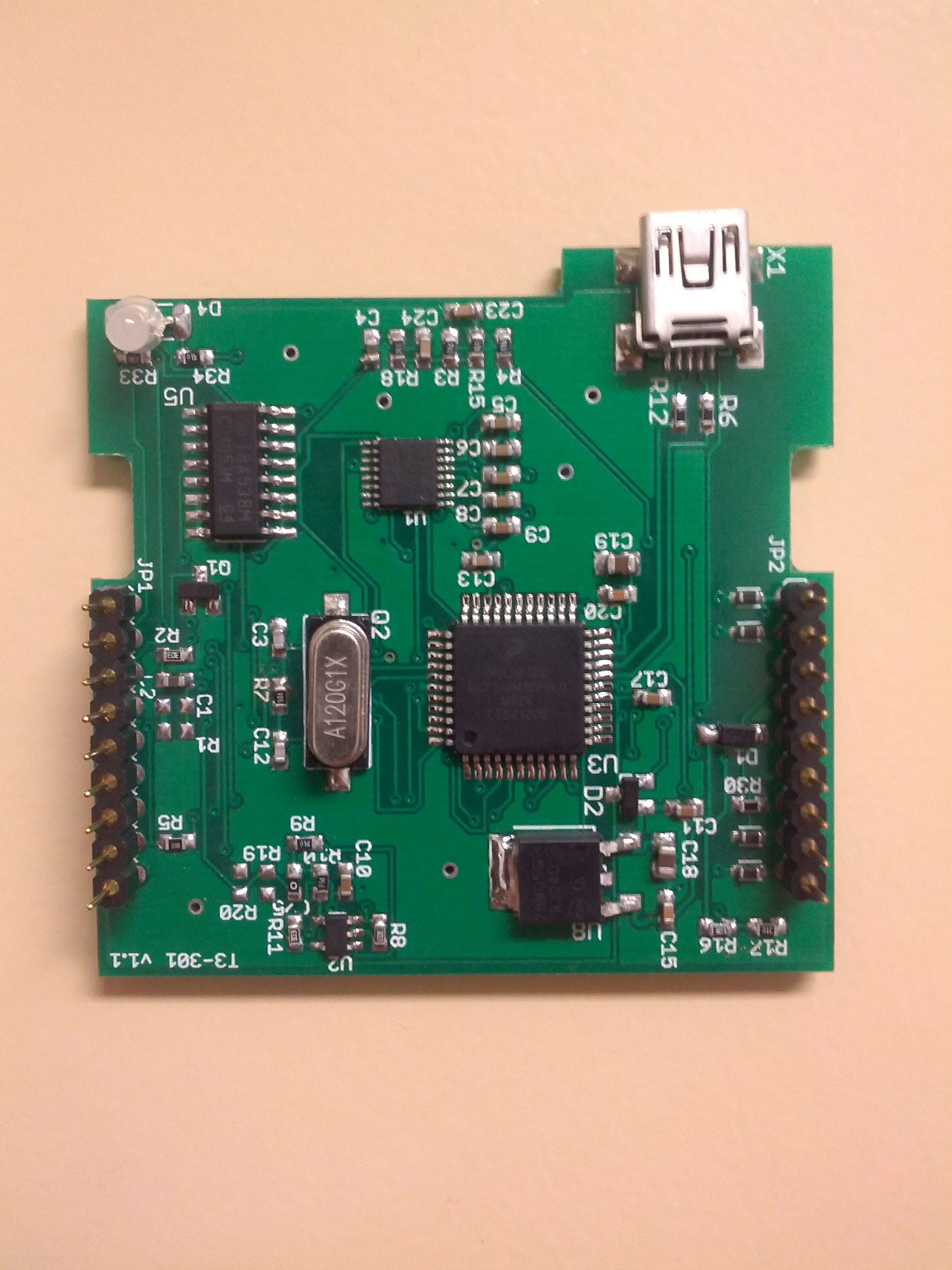
| 01:52, 11 November 2012 | T3-301 Daughter board.jpg (file) |  |
1.41 MB | AI6MS | This is the Tracker3 daughter board that fits inside the FC-301 D Transceiver. | 1 |
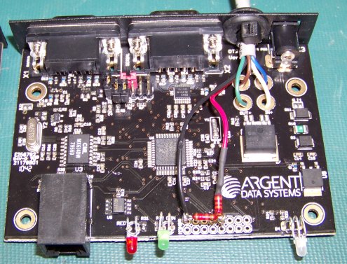
| 05:59, 7 October 2009 | T2 LCD-harness-in-T2-sm.png (file) |  |
1.36 MB | N7FMH | One example of terminating the LCD harness in the T2. | 1 |
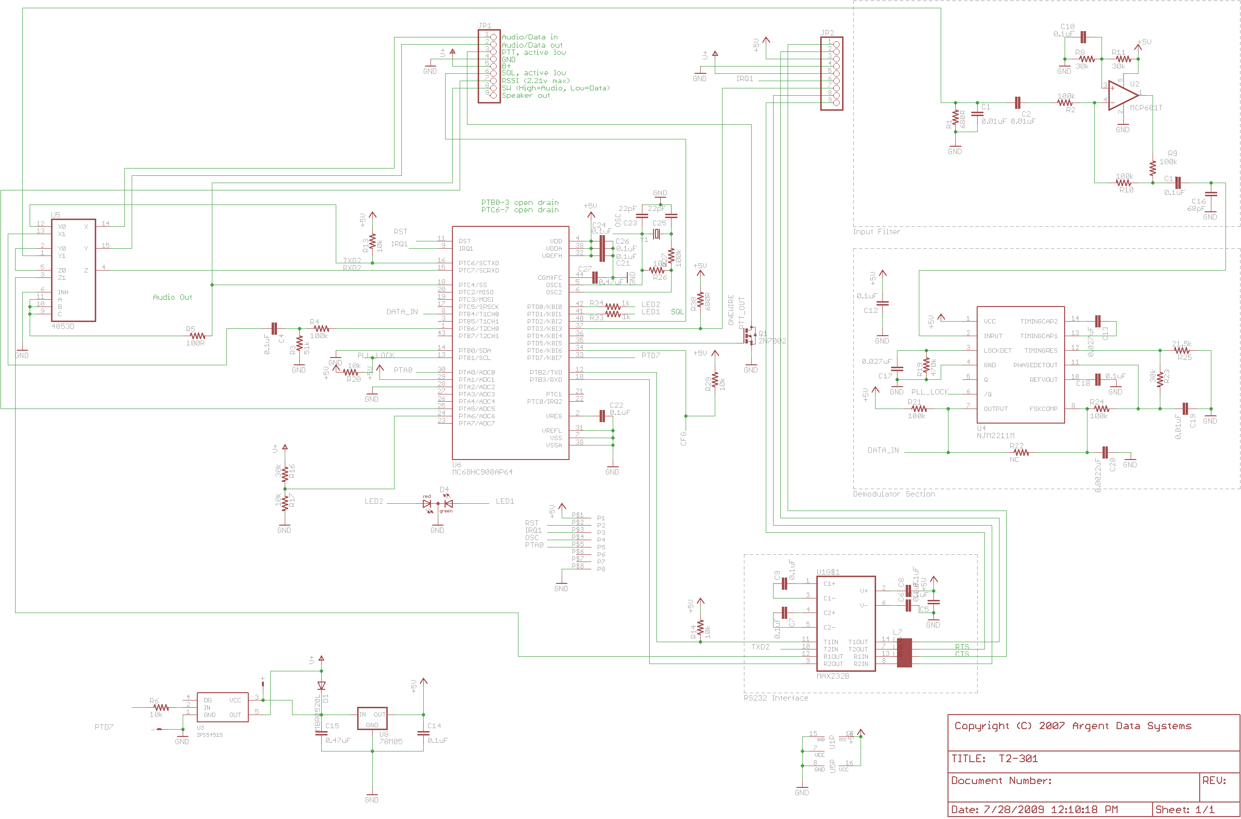
| 12:12, 26 April 2010 | T2-301-schematic.png (file) |  |
77 KB | ScottN1VG | T2-301 v1.1 schematic | 1 |
| 12:55, 16 June 2009 | T2-20x4.jpg (file) |  |
58 KB | ScottN1VG | Tracker2 LCD display | 1 |
| 14:04, 20 May 2009 | T2-135-v1 2.png (file) |  |
89 KB | ScottN1VG | T2-135 v1.2 Schematic | 1 |
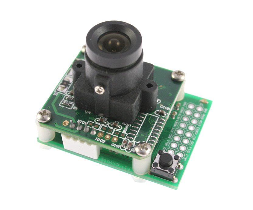
| 13:47, 25 May 2011 | Sstvcam v1.1.jpg (file) |  |
81 KB | ScottN1VG | SSTVCAM v1.1 | 1 |
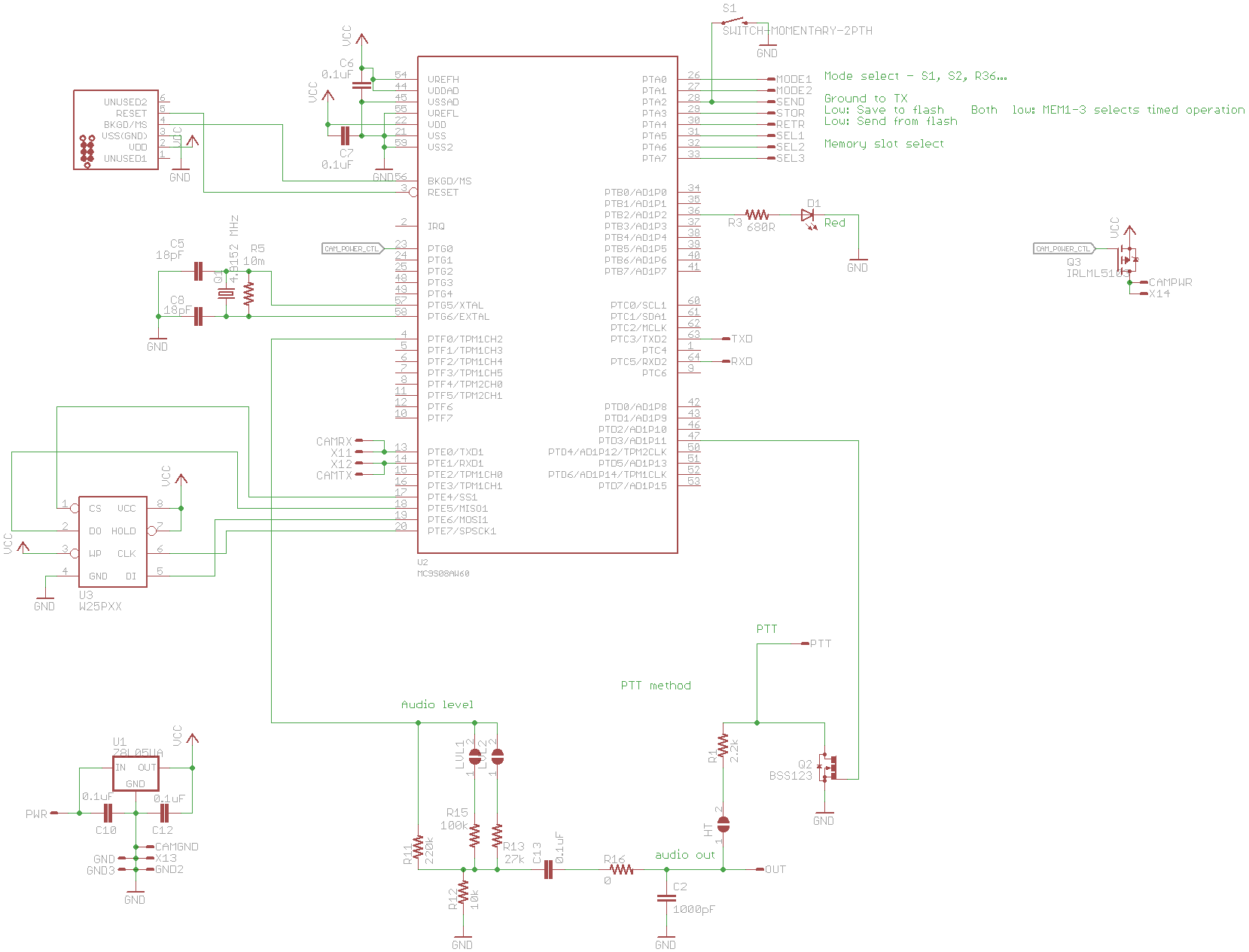
| 15:19, 13 February 2013 | Sstvcam schematic.png (file) |  |
43 KB | ScottN1VG | SSTVcam Schematic | 1 |
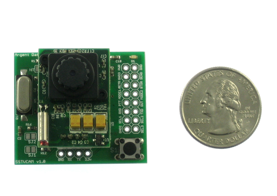
| 16:21, 12 January 2011 | Sstvcam.jpg (file) |  |
148 KB | ScottN1VG | SSTVCAM 1.0 | 1 |
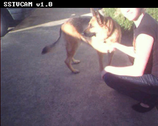
| 16:53, 12 January 2011 | Sstvcam-capture1.jpg (file) |  |
40 KB | ScottN1VG | Sample image capture by SSTVCAM in Scottie 1 mode | 1 |
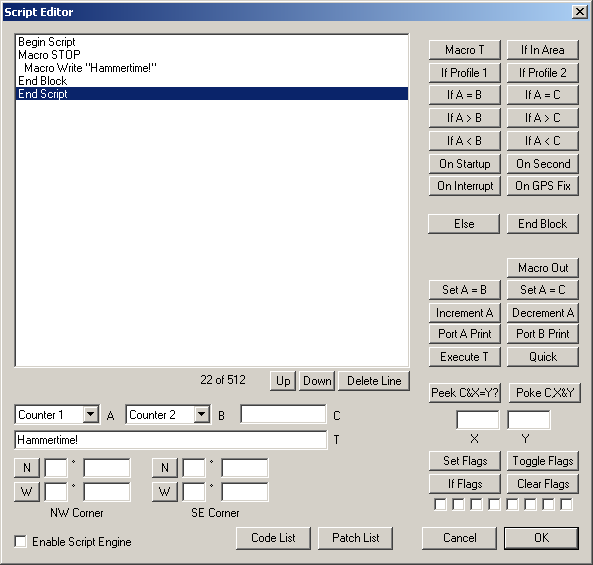
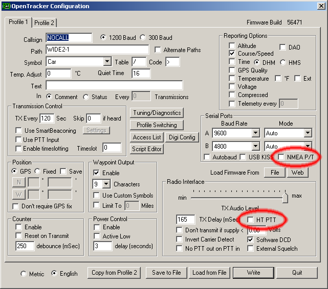
| 18:28, 22 February 2009 | ScriptEditor.png (file) |  |
16 KB | ScottN1VG | Script editor dialog in otwincfg | 1 |
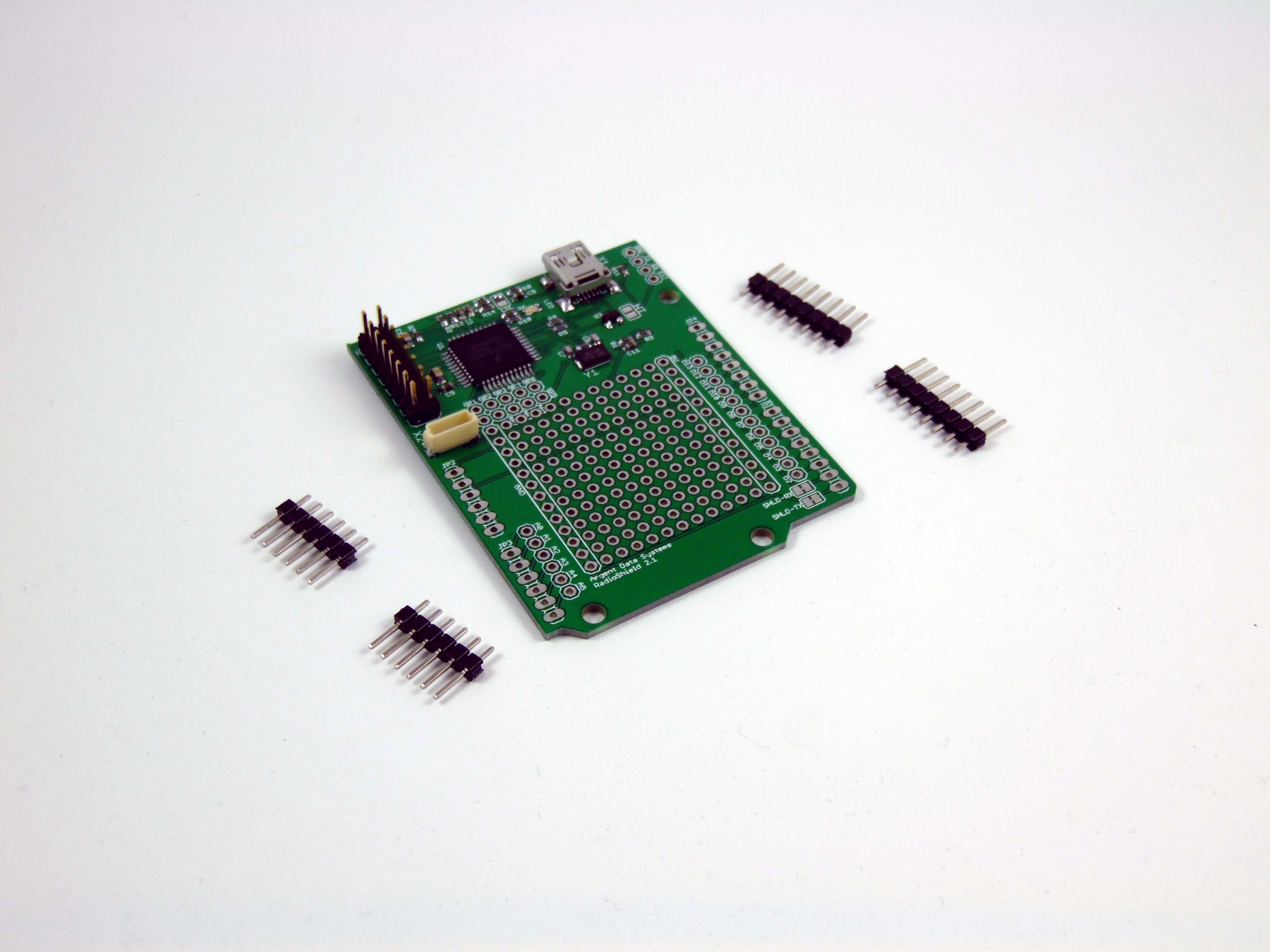
| 14:15, 27 January 2016 | Radioshield2.jpg (file) |  |
654 KB | Kg6lhy | 1 | |
| 13:16, 27 January 2016 | Radioshield2.JPG (file) |  |
4.88 MB | Kg6lhy | 1 | |
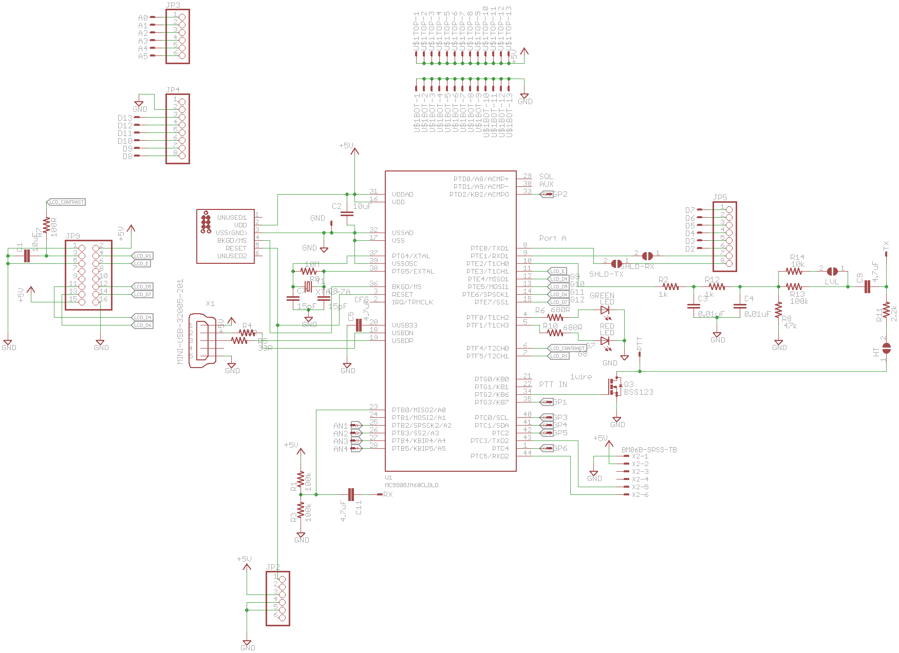
| 12:54, 27 January 2016 | Radioshield2-schematic.png (file) |  |
52 KB | Kg6lhy | 1 | |
| 13:48, 12 April 2010 | Radioshield.jpg (file) |  |
93 KB | ScottN1VG | Assembled Radio Shield with Arduino and LCD module | 1 |
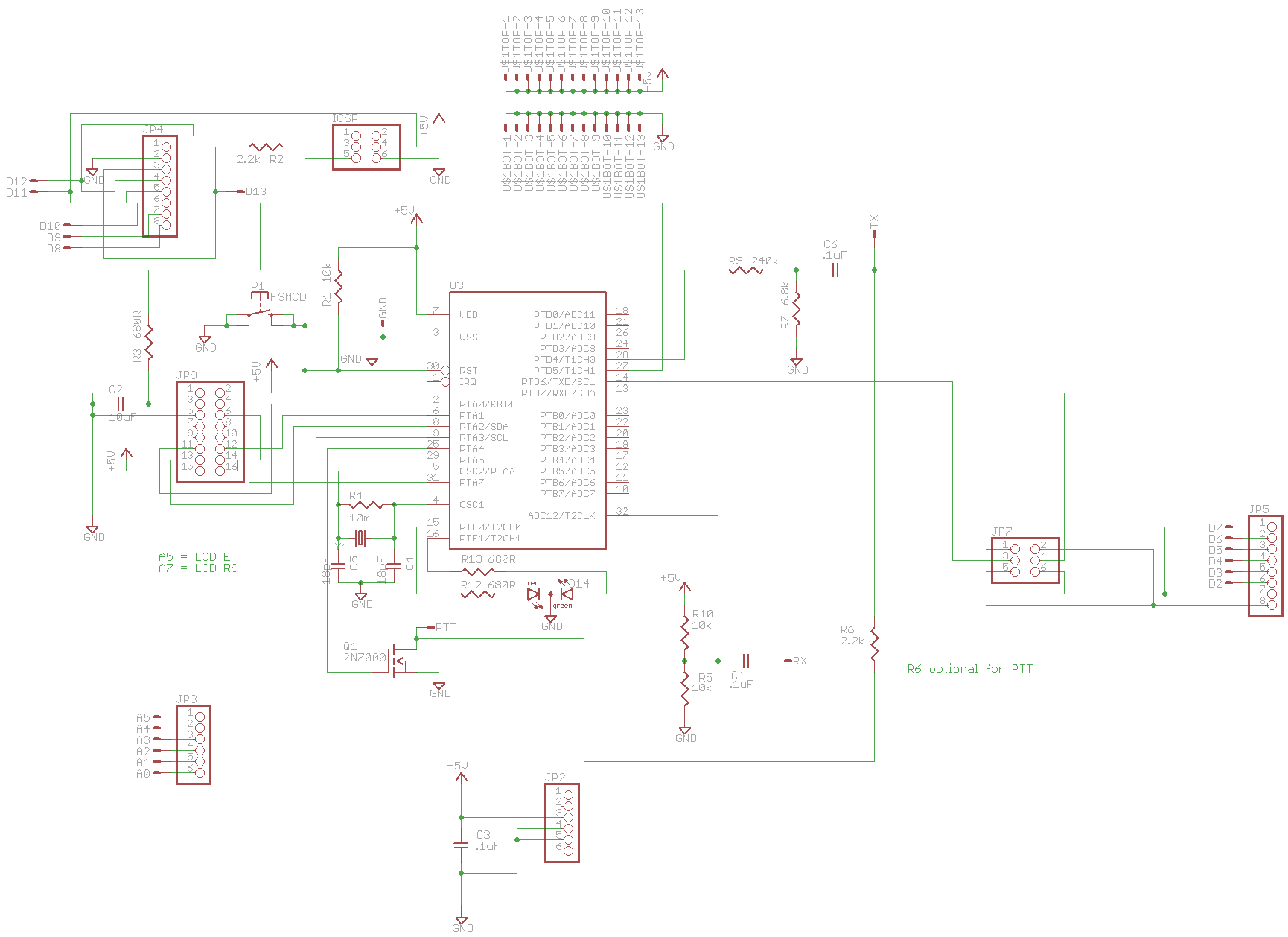
| 12:54, 27 January 2016 | Radioshield-schematic.png (file) |  |
40 KB | Kg6lhy | Reverted to version as of 21:22, 27 April 2010 | 3 |
| 13:51, 13 September 2019 | Phxboot4.jpg (file) |  |
3.22 MB | ScottN1VG | 1 | |
| 13:51, 13 September 2019 | Phxboot3.jpg (file) |  |
467 KB | ScottN1VG | 1 | |
| 13:50, 13 September 2019 | Phxboot2.jpg (file) |  |
552 KB | ScottN1VG | 1 | |
| 13:50, 13 September 2019 | Phxboot1.jpg (file) |  |
968 KB | ScottN1VG | 1 | |
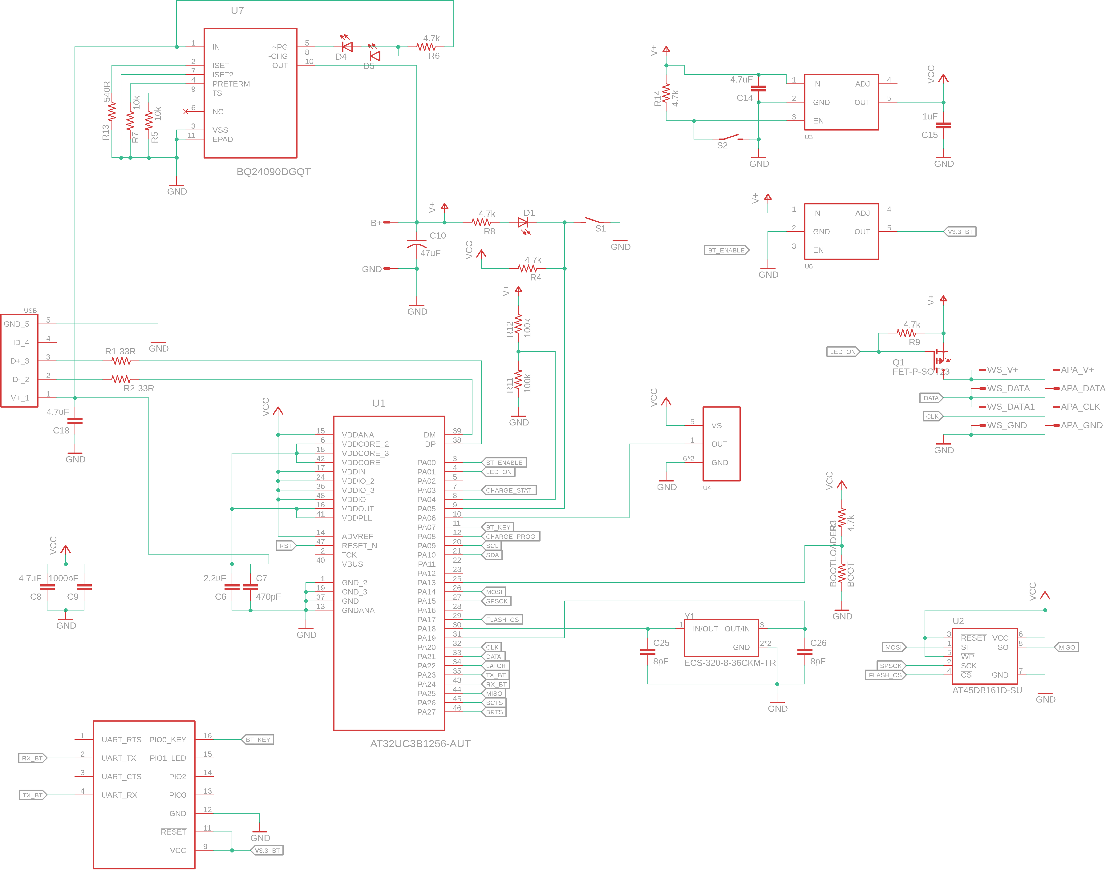
| 12:22, 13 September 2019 | Phx12 sch.png (file) |  |
118 KB | ScottN1VG | Phoenix retrofit v1.2 schematic | 1 |
| 12:22, 13 September 2019 | Phx12 brd.png (file) |  |
24 KB | ScottN1VG | Phoenix retrofit board v1.2 | 1 |
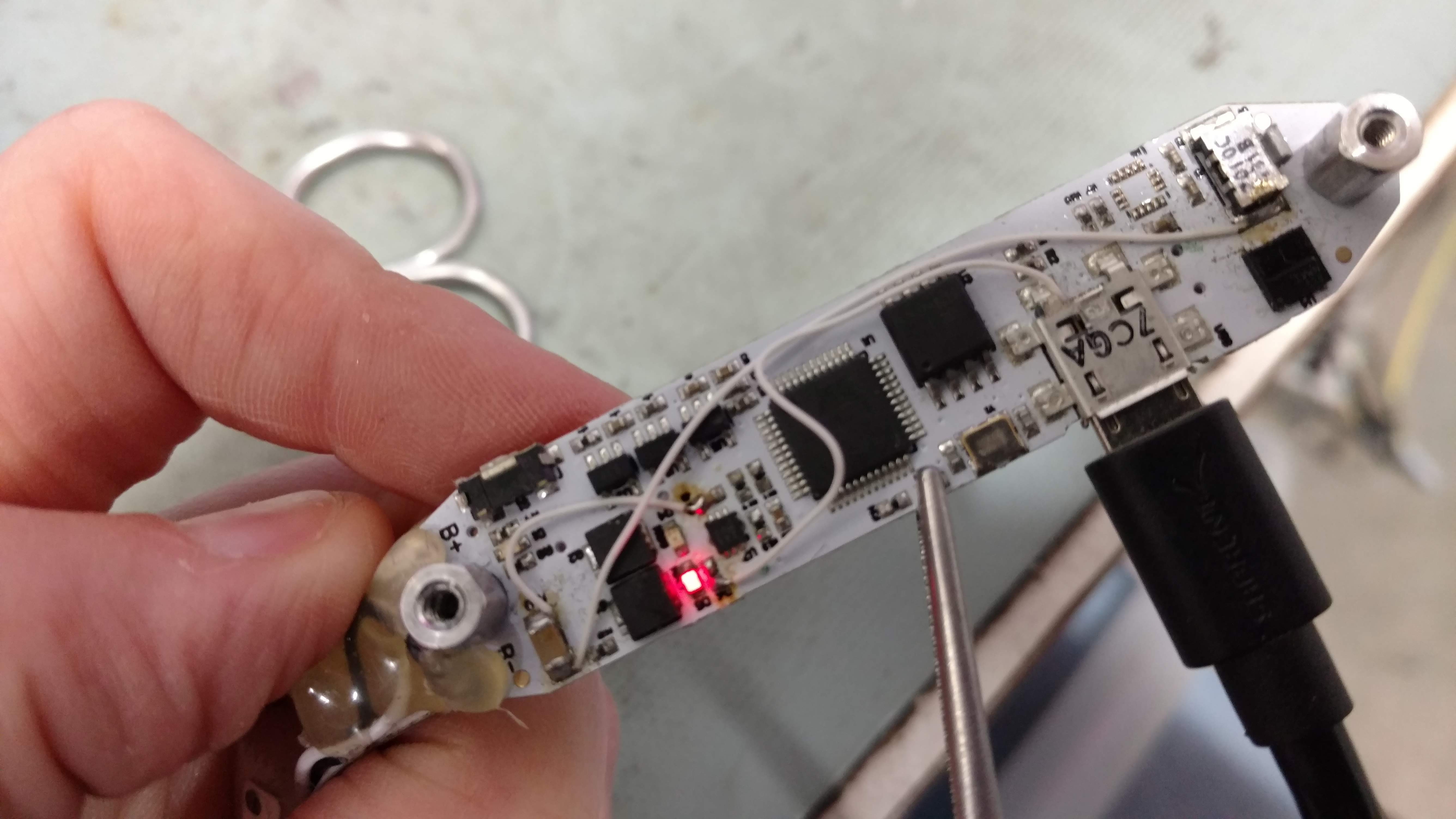
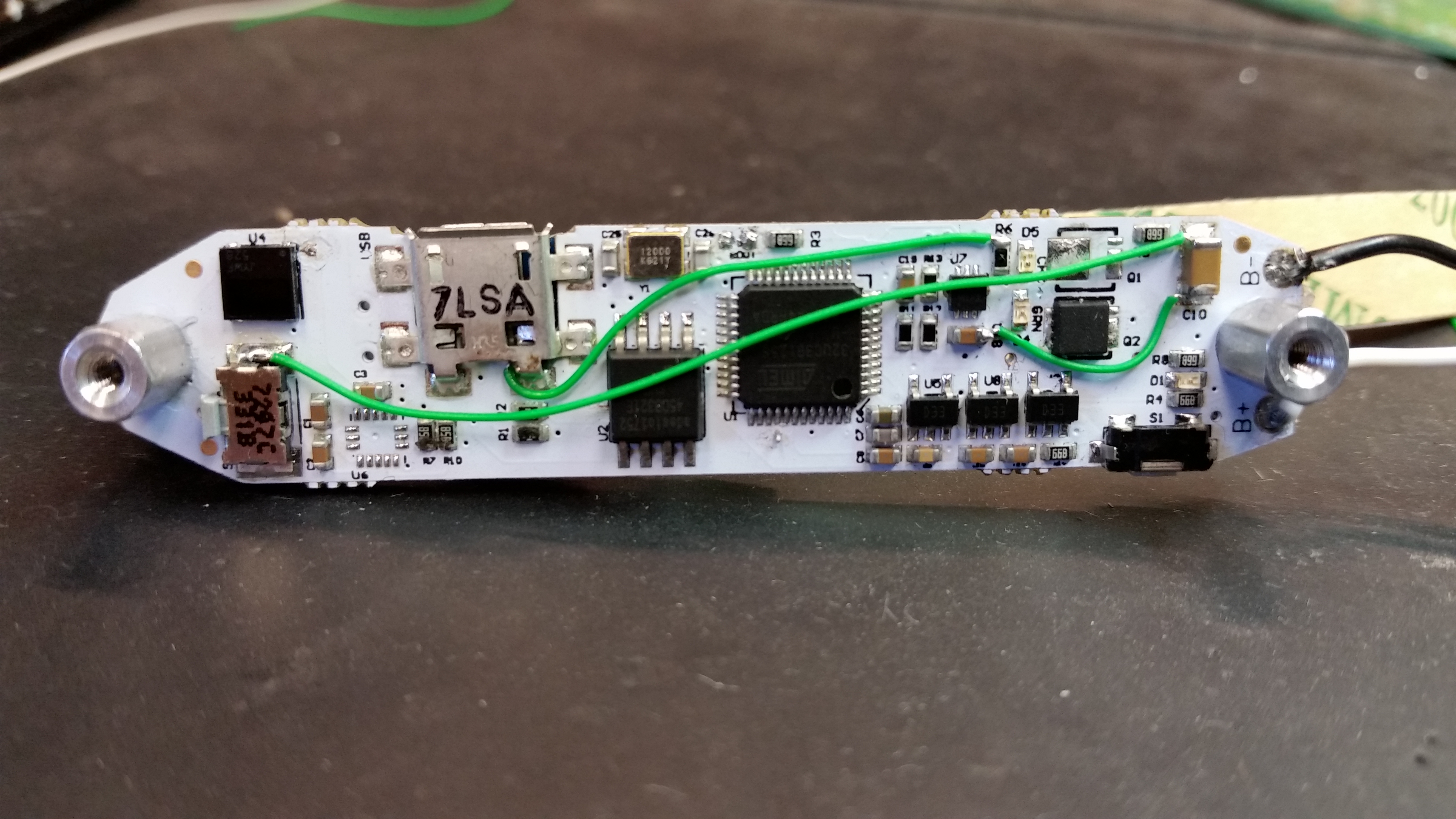
| 11:59, 13 September 2019 | PHX retrofit.jpg (file) |  |
3.45 MB | ScottN1VG | Illustration of wires to be added to 2016 model Phoenix board | 1 |
| 13:31, 13 September 2019 | PHX reset.jpg (file) |  |
174 KB | ScottN1VG | Phoenix hoop internal reset button | 1 |
| 11:52, 1 July 2013 | Otwincfg-micro.png (file) |  |
27 KB | ScottN1VG | 1 | |
| 13:40, 11 June 2009 | Otwincfg-main.gif (file) |  |
24 KB | ScottN1VG | OTWINCFG Main Screen | 1 |
| 13:29, 11 June 2009 | Otwincfg-connect.gif (file) |  |
7 KB | ScottN1VG | OTWINCFG Connect Dialog | 1 |
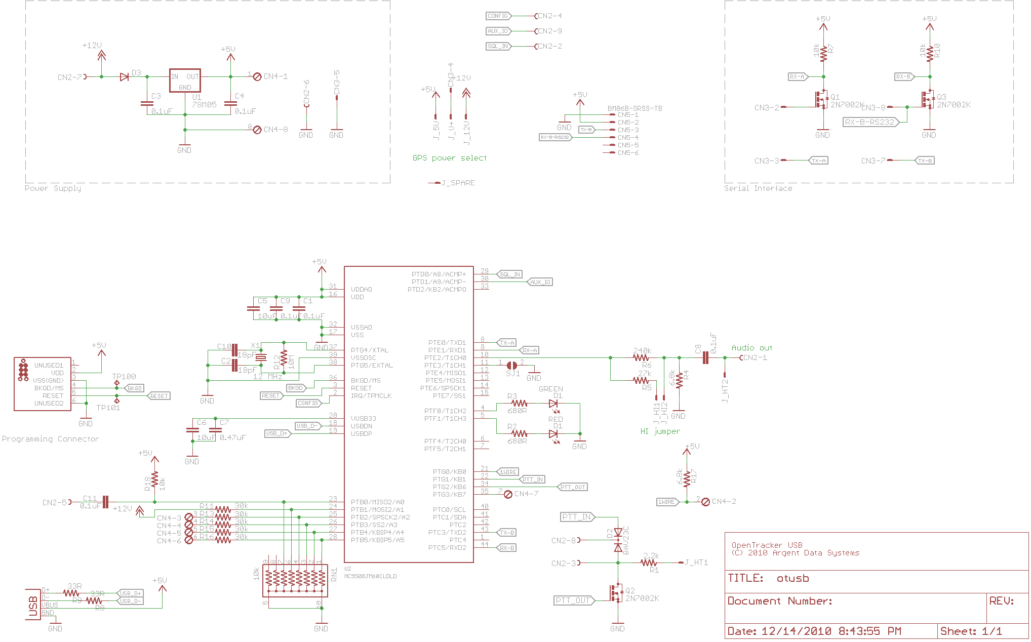
| 21:53, 14 December 2010 | Otusb-schematic.png (file) |  |
57 KB | ScottN1VG | OpenTracker USB v1.1 schematic. Changes from v1.0: Added jumper SJ1 for TTL mode selection Corrected CN5 (GPS connector) pinout | 1 |
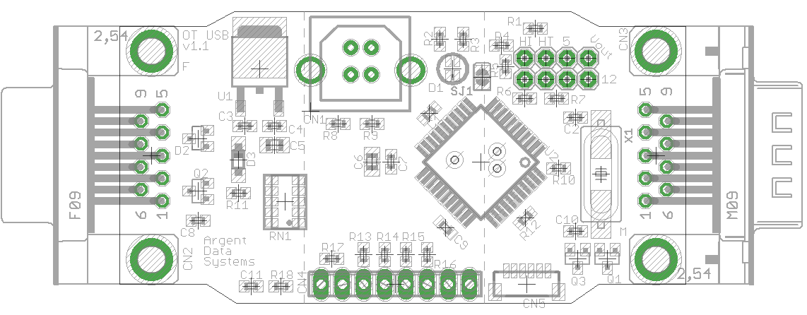
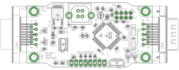
| 21:55, 14 December 2010 | Otusb-layout.png (file) |  |
45 KB | ScottN1VG | OpenTracker USB v1.1 layout | 1 |
| 21:18, 1 March 2009 | Otplus-smt.jpg (file) |  |
45 KB | VE6SRV | OT+ SMT | 1 |
| 21:16, 1 March 2009 | Otplus-rev1 1.jpg (file) |  |
260 KB | VE6SRV | OT+ rev 1.1 | 1 |
| 21:53, 14 December 2010 | Otplus-layout.png (file) |  |
19 KB | ScottN1VG | OpenTracker USB v1.1 board layout | 1 |
| 21:15, 1 March 2009 | Otplus-case.jpg (file) |  |
79 KB | VE6SRV | OT+ case | 1 |
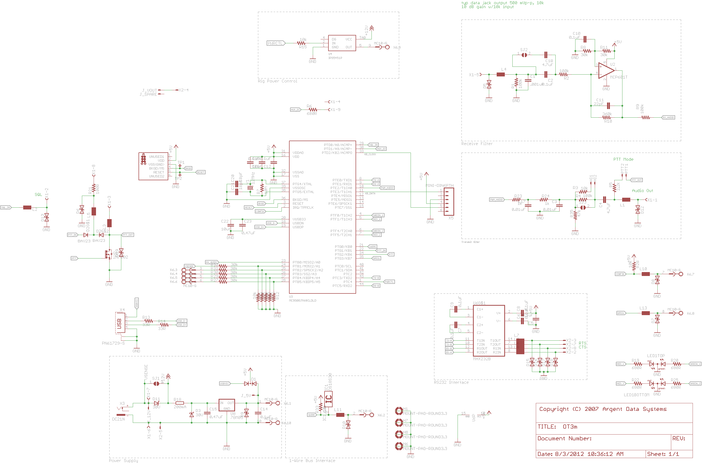
| 09:21, 12 April 2016 | Ot3m schematic.png (file) |  |
96 KB | ScottN1VG | Schematic for the Tracker3 model OT3m | 1 |
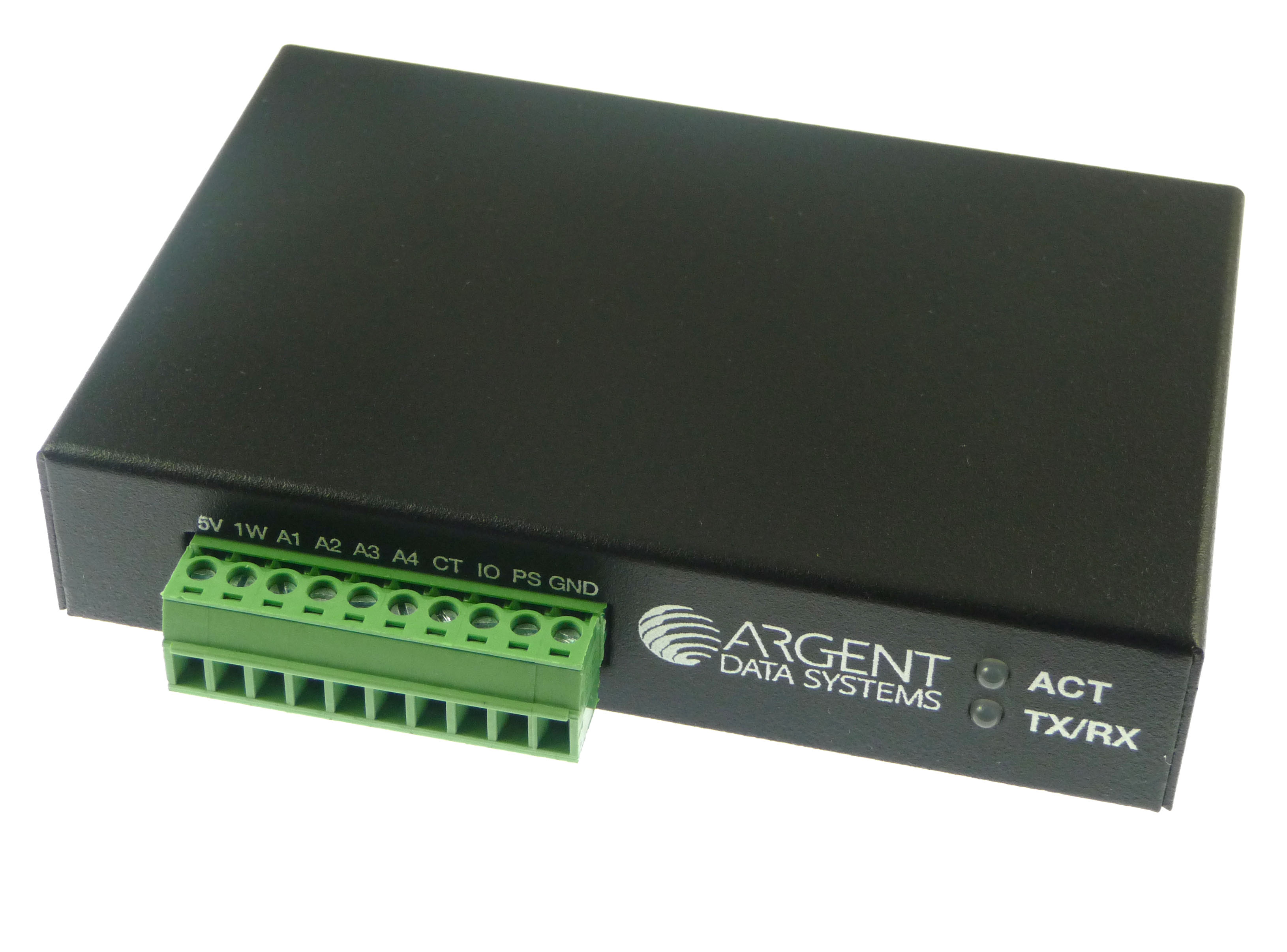
| 12:27, 5 January 2012 | Ot3m-termblk.jpg (file) |  |
586 KB | ScottN1VG | OT3m with terminal block installed | 1 |
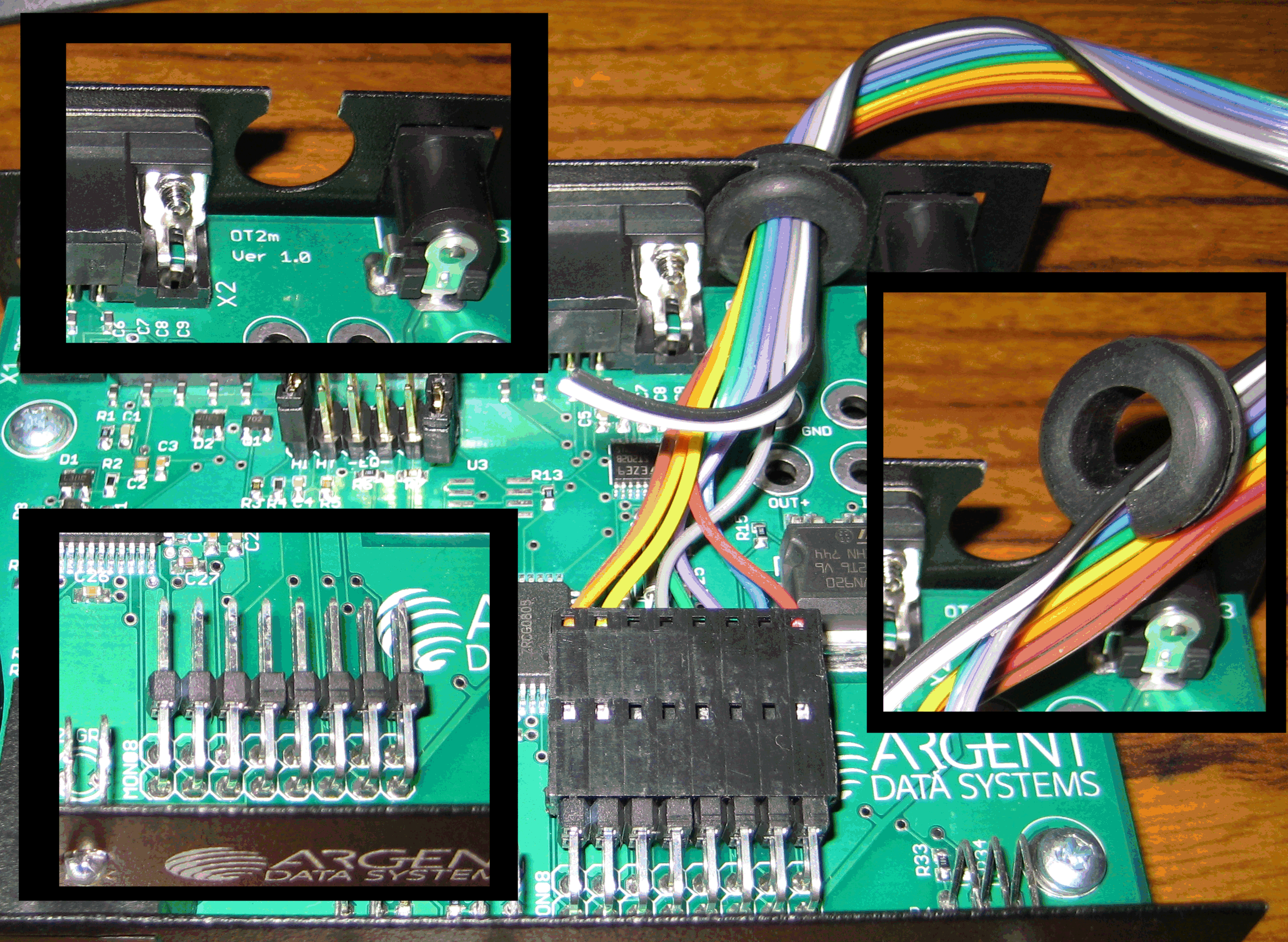
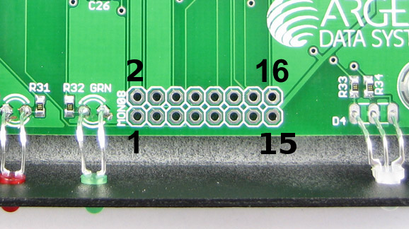
| 00:37, 26 June 2009 | Ot2m-mon08.jpg (file) |  |
83 KB | Oh7lzb | OT2m MON08 programming header with pin markings | 2 |
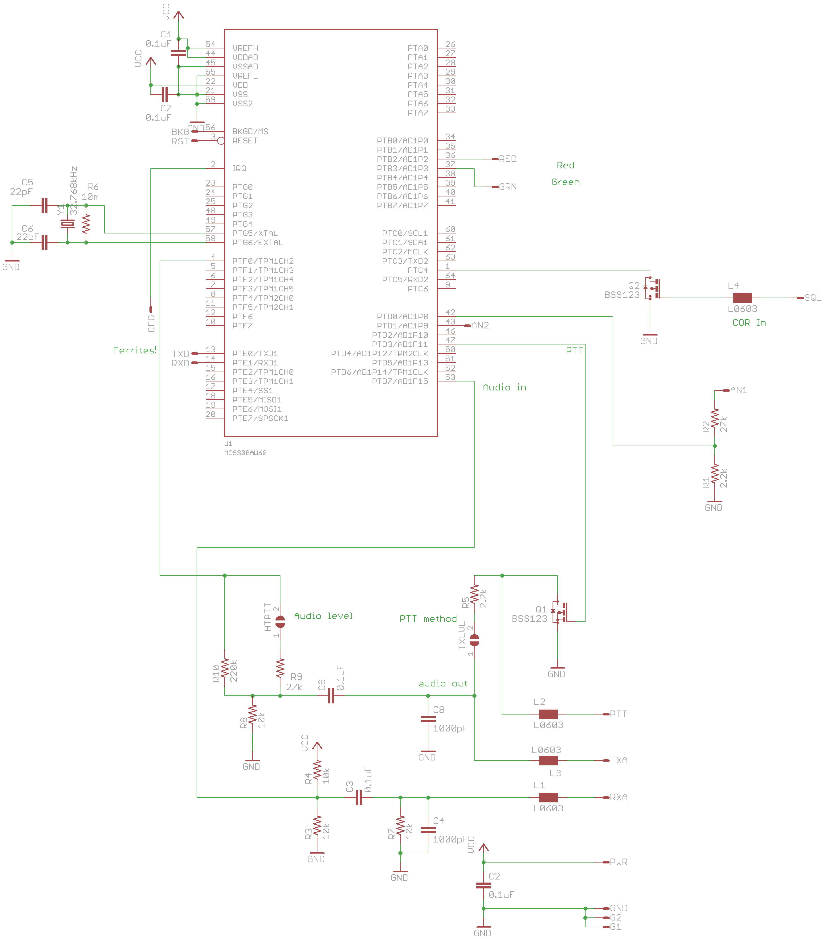
| 16:19, 22 February 2009 | Ot1plus rt schematic.png (file) |  |
90 KB | ScottN1VG | OpenTracker+ RT v1.0 Schematic | 2 |
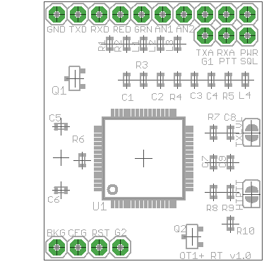
| 16:17, 22 February 2009 | Ot1plus rt layout.png (file) |  |
7 KB | ScottN1VG | OpenTracker+ RT v1.0 layout | 1 |
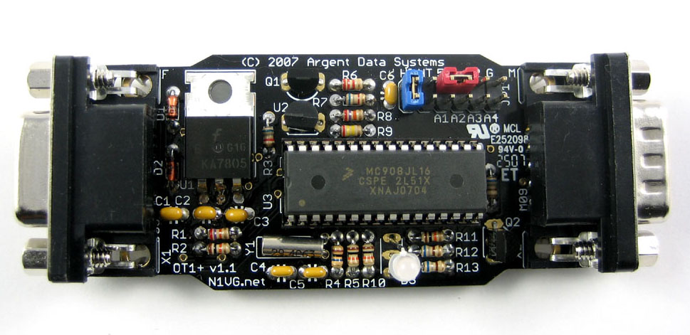
| 08:16, 1 June 2009 | Ot1plus-v1 1.jpg (file) |  |
105 KB | ScottN1VG | OpenTracker+ board | 1 |
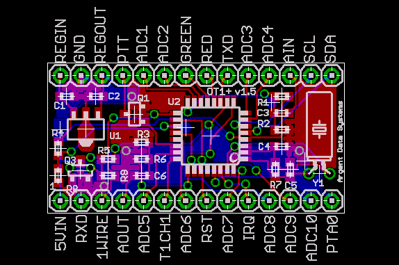
| 15:58, 22 February 2009 | Ot1plus-smt-1 5.png (file) |  |
20 KB | ScottN1VG | OpenTracker+ SMT v1.5 layout | 1 |
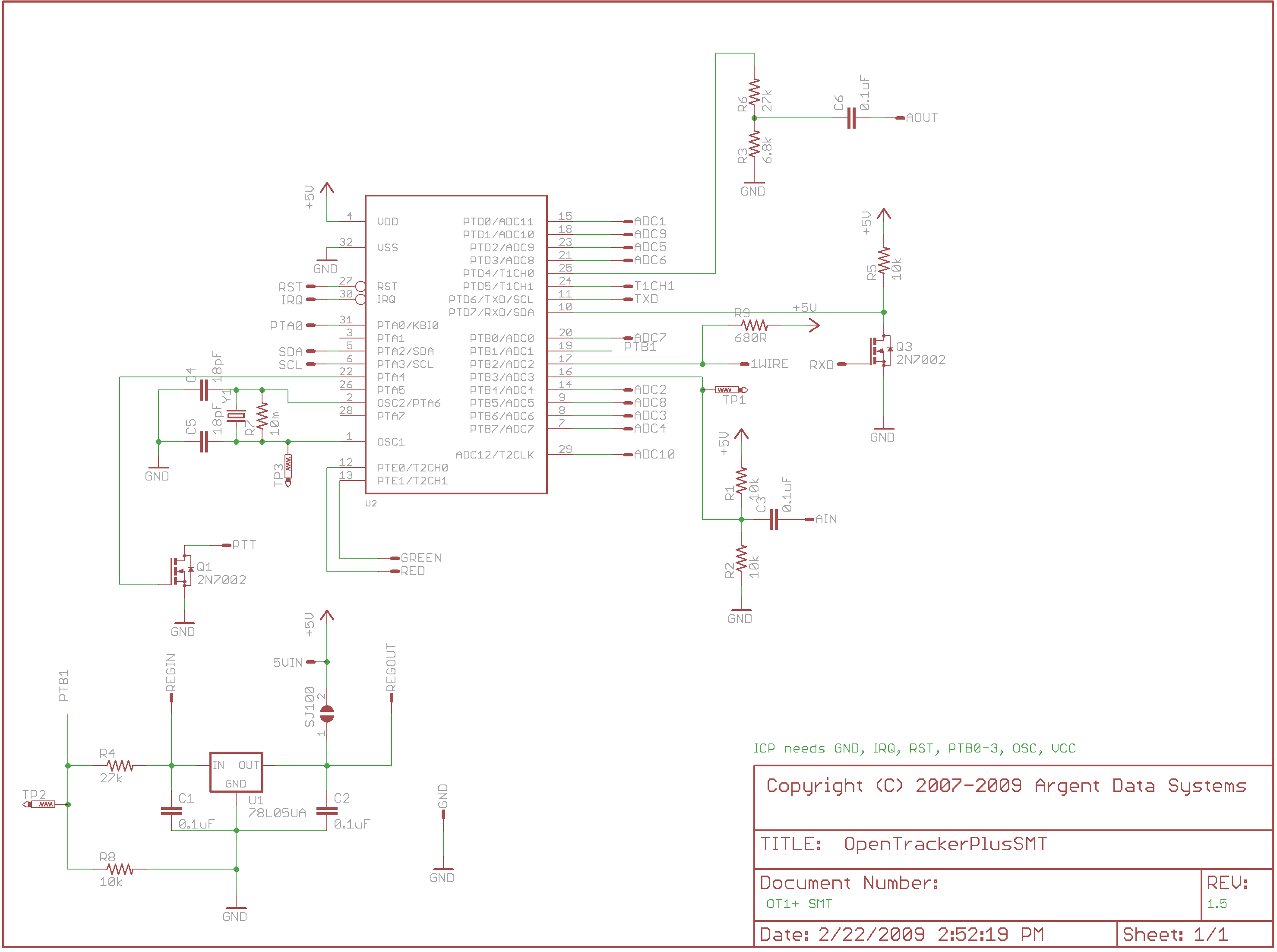
| 15:55, 22 February 2009 | Ot1plus-smt-1 5-schematic.png (file) |  |
74 KB | ScottN1VG | OT1+ SMT v1.5 schematic | 2 |
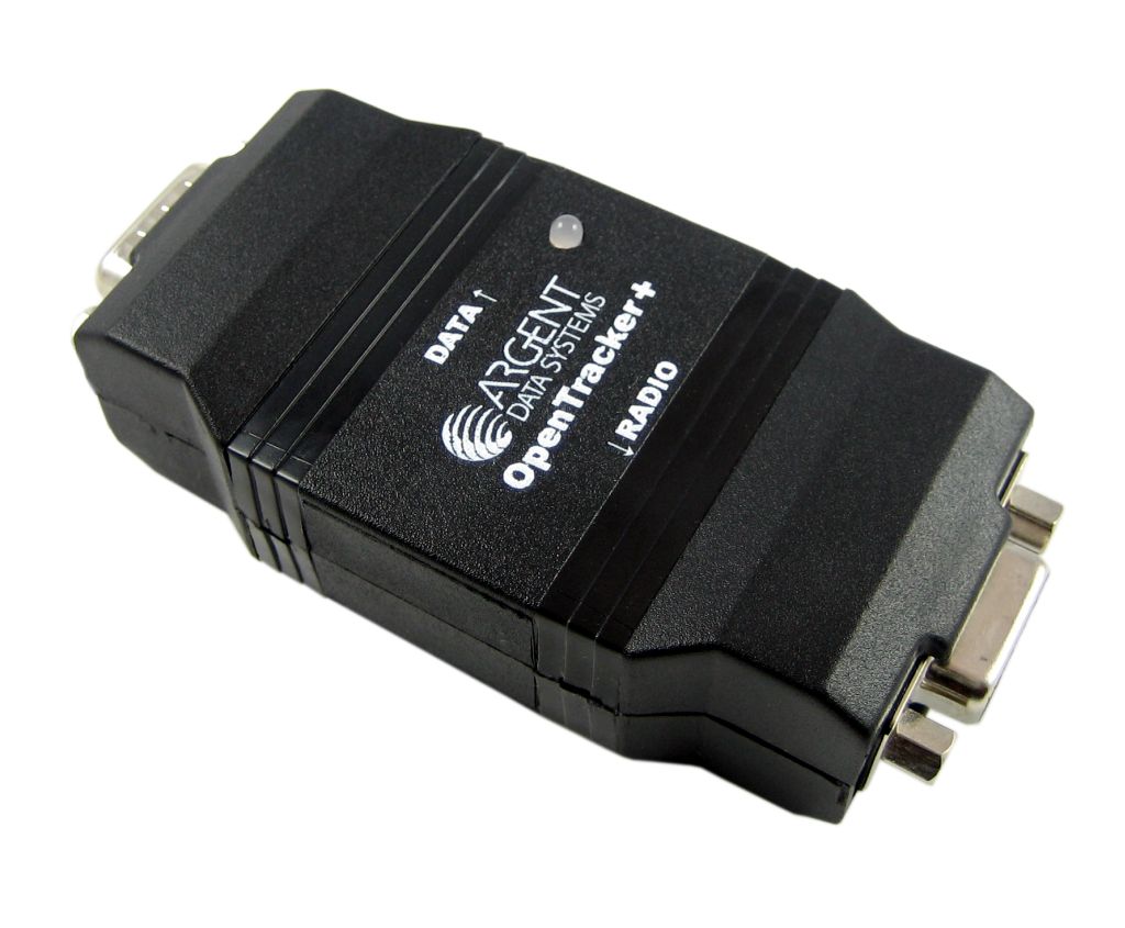
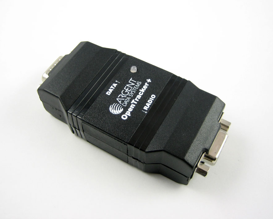
| 08:17, 1 June 2009 | Ot1plus-assembled.jpg (file) |  |
69 KB | ScottN1VG | OpenTracker+ assembled in case | 1 |
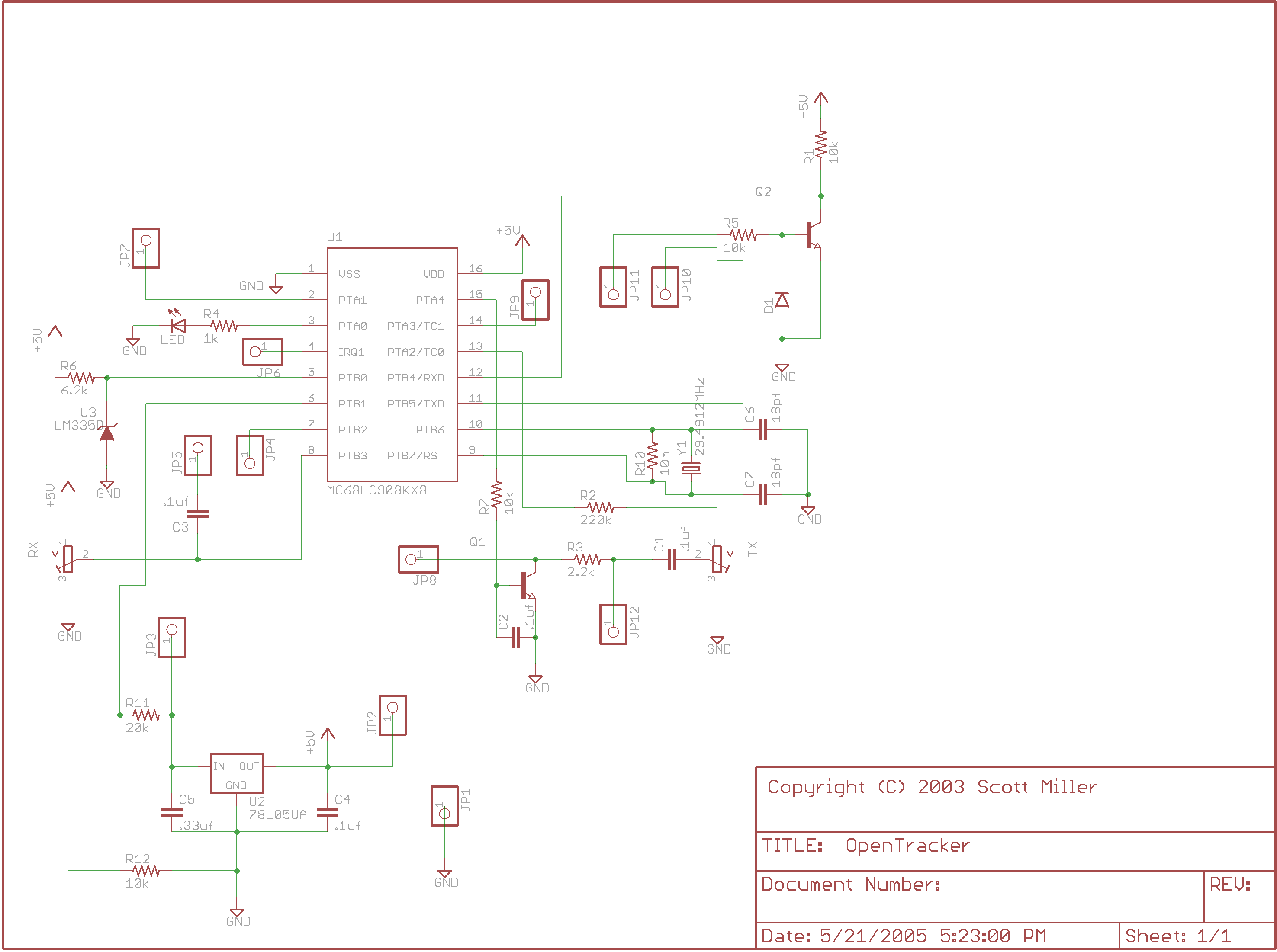
| 17:52, 14 July 2016 | Ot1-smt-schematic.png (file) |  |
64 KB | ScottN1VG | 1 | |
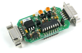
| 17:51, 14 July 2016 | Opentracker1x.jpg (file) |  |
29 KB | ScottN1VG | 1 |
First page |
Previous page |
Next page |
Last page |