File list
From ArgentWiki
This special page shows all uploaded files.
First page |
Previous page |
Next page |
Last page |
| Date | Name | Thumbnail | Size | User | Description | Versions |
|---|---|---|---|---|---|---|
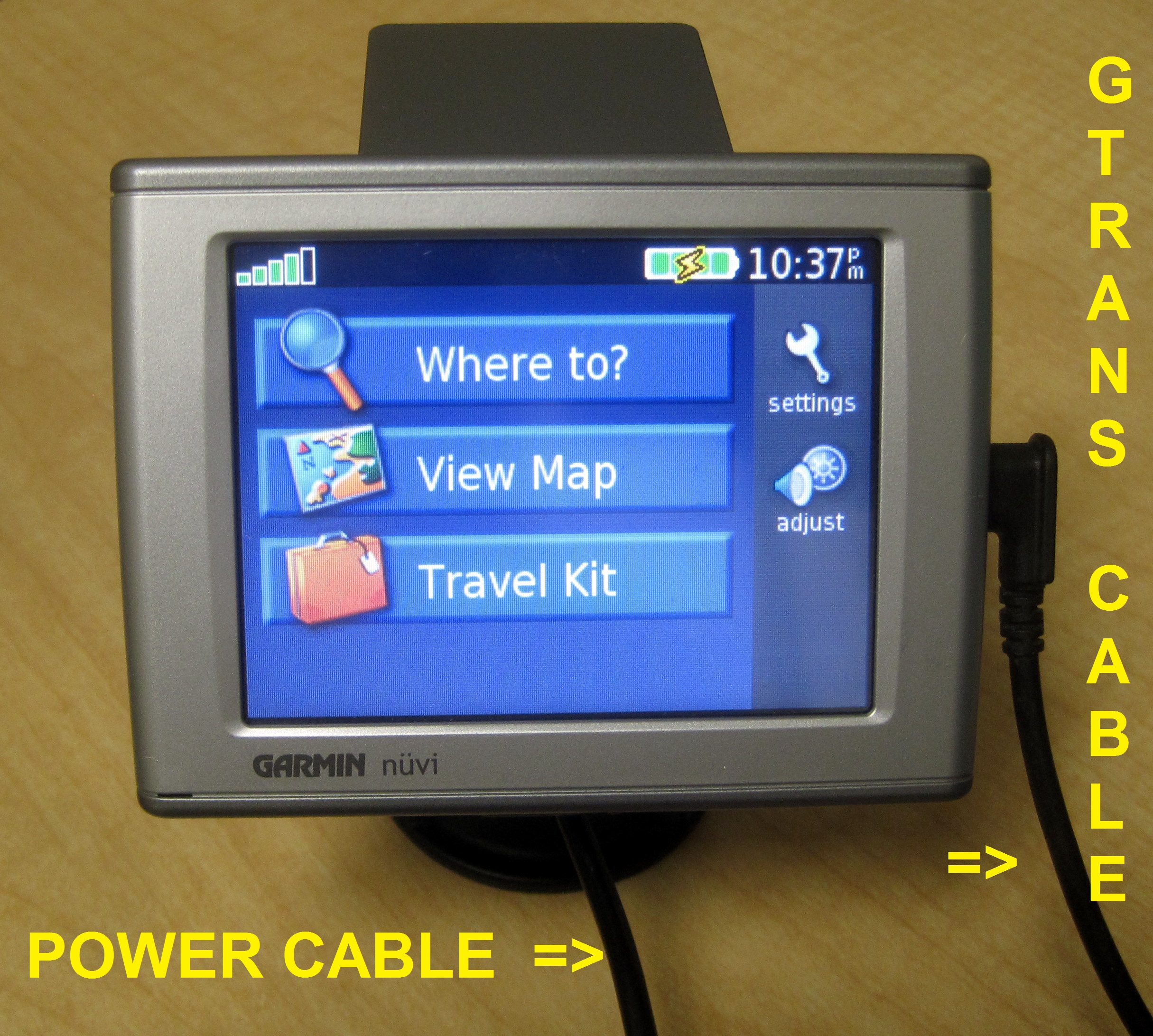
| 23:23, 11 March 2012 | Nuvi 350 - Device Labled.JPG (file) |  |
1.38 MB | AI6MS | 1 | |
| 23:07, 11 March 2012 | Nuvi 350 - Where to Screen.JPG (file) |  |
1.28 MB | AI6MS | 1 | |
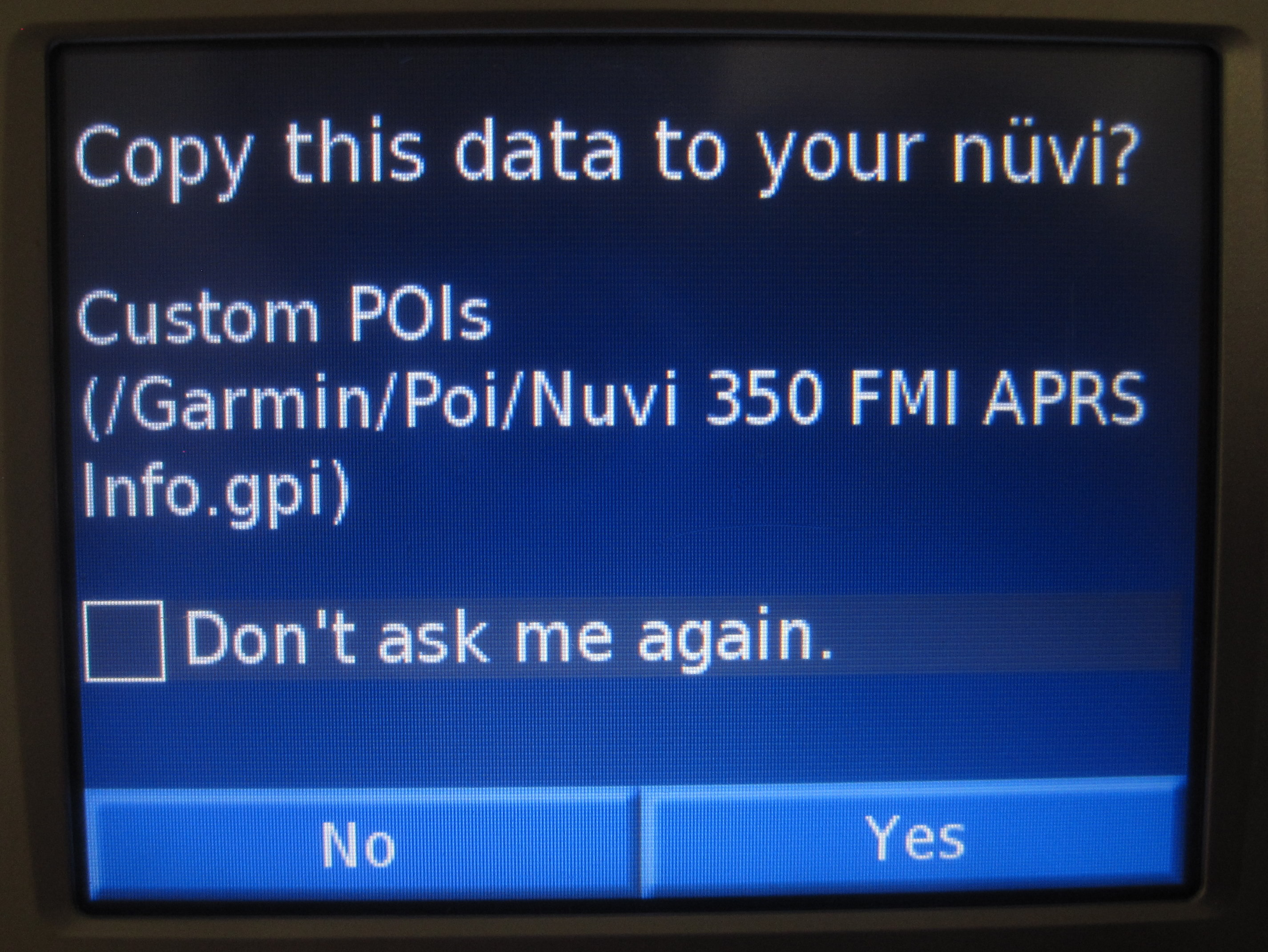
| 23:07, 11 March 2012 | Nuvi 350 - POI Copy Prompt.JPG (file) |  |
1.17 MB | AI6MS | 1 | |
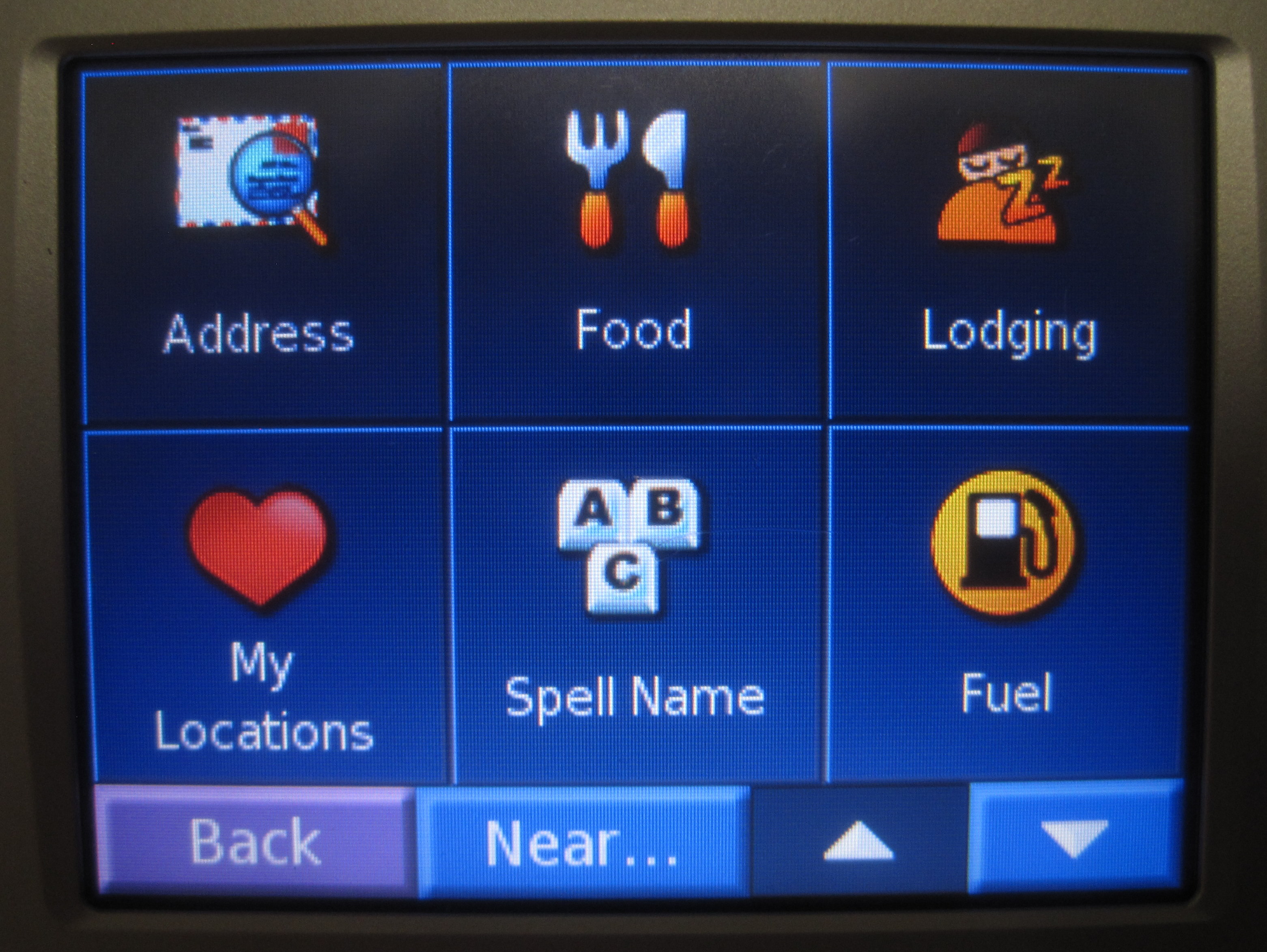
| 23:07, 11 March 2012 | Nuvi 350 - POI in Where to Menu.JPG (file) |  |
1.32 MB | AI6MS | 1 | |
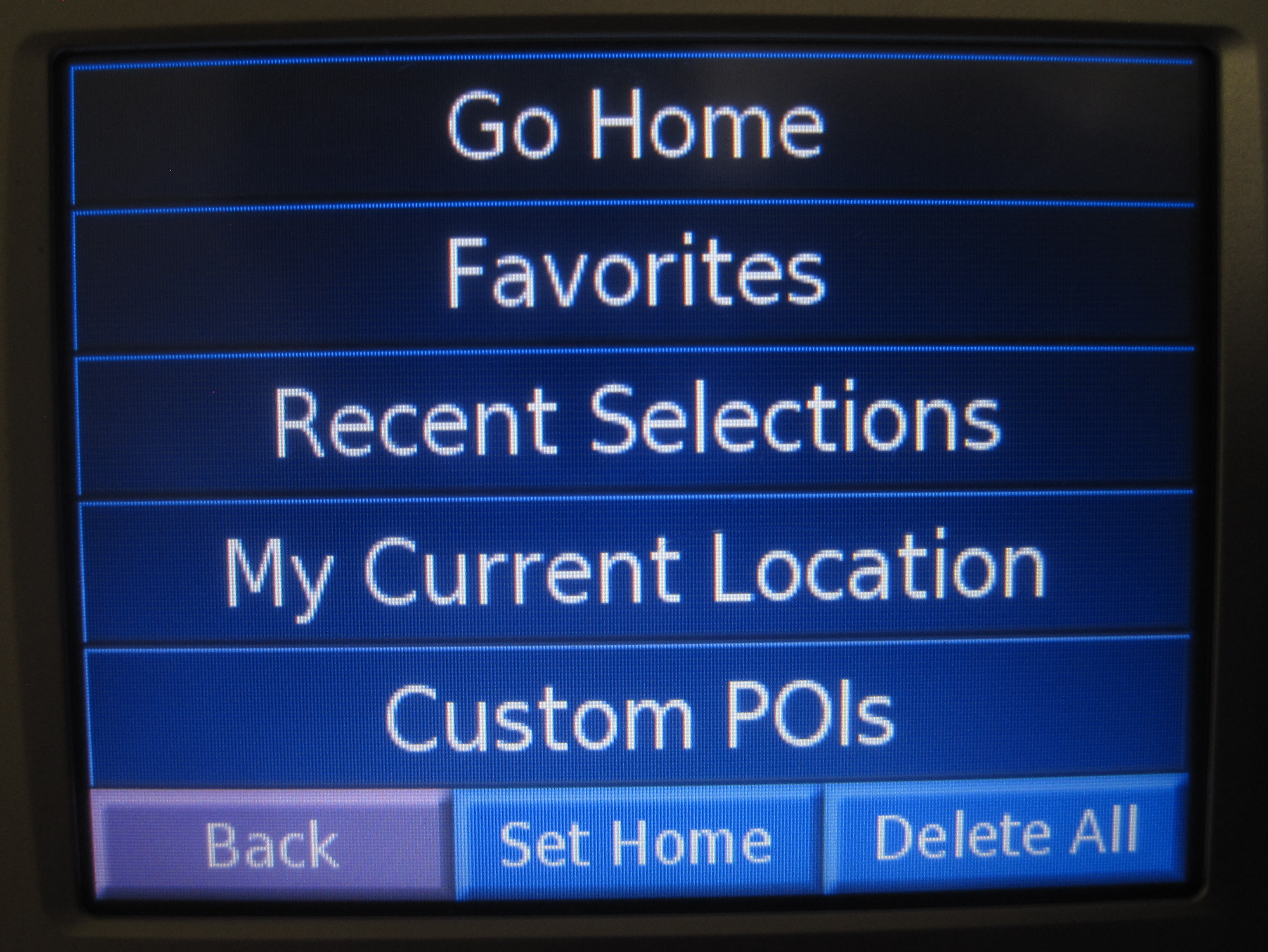
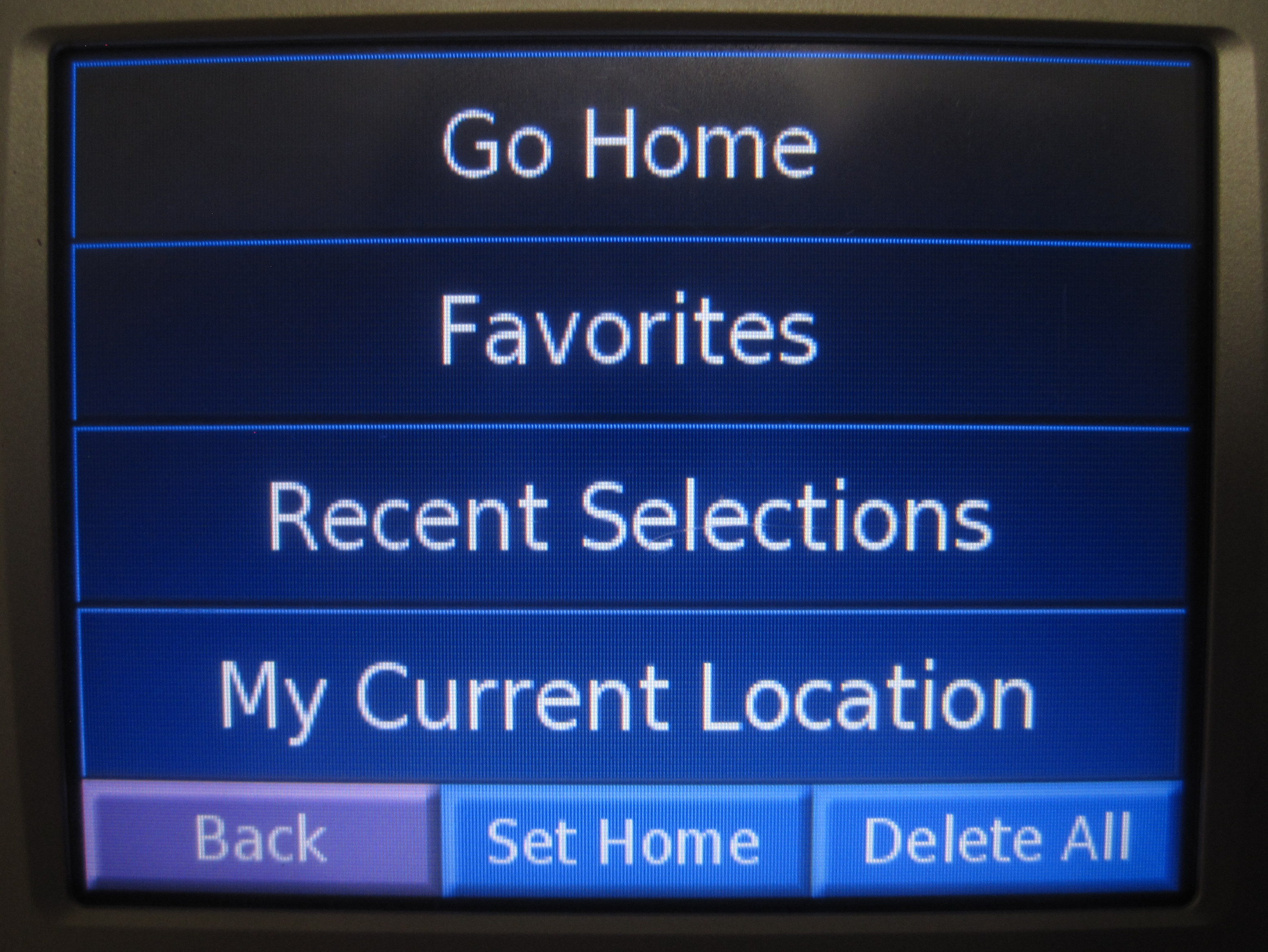
| 23:07, 11 March 2012 | Nuvi 350 - My Locations Screen.JPG (file) |  |
1.25 MB | AI6MS | 1 | |
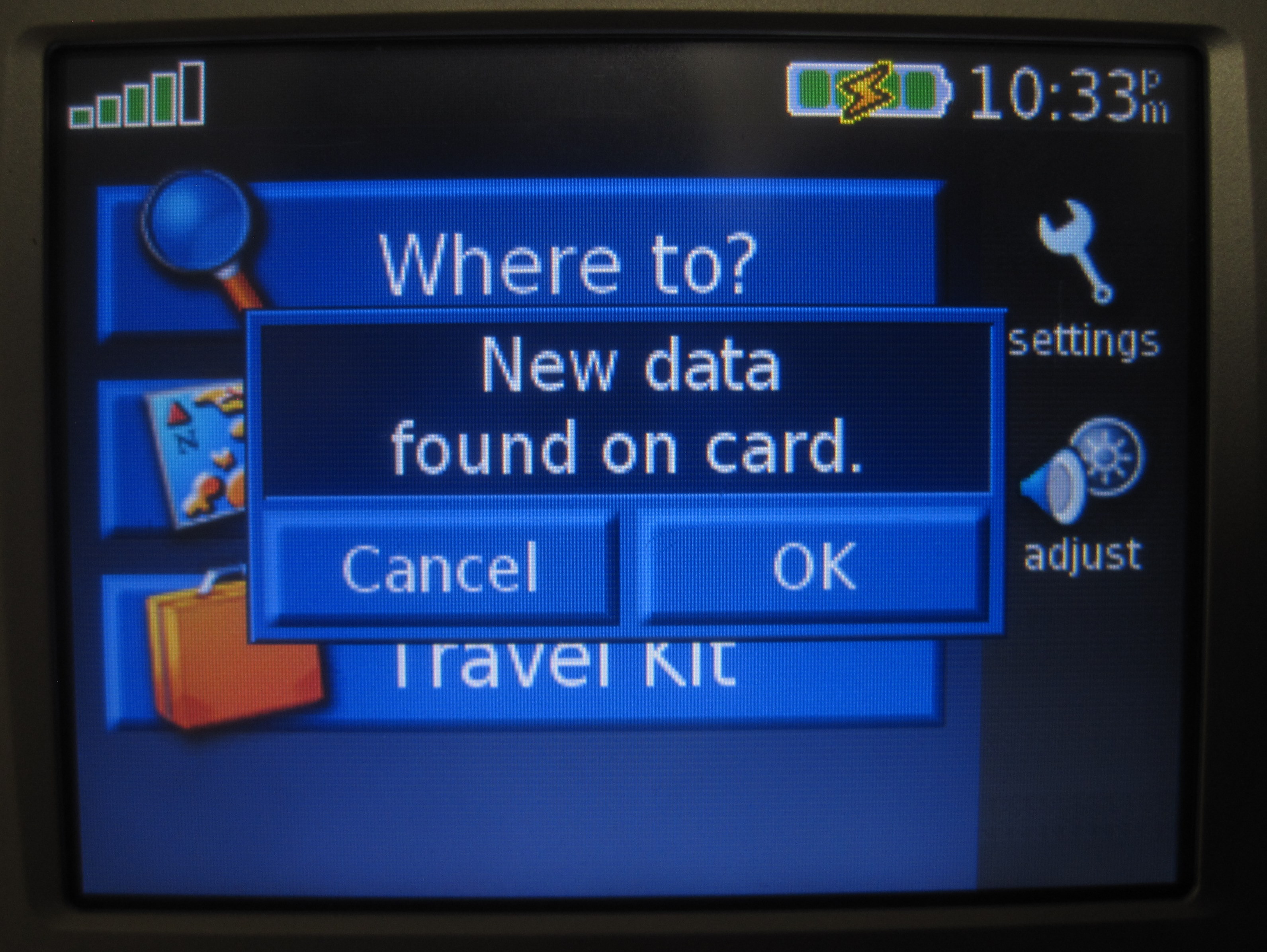
| 23:07, 11 March 2012 | Nuvi 350 - POI Data Found.JPG (file) |  |
1.12 MB | AI6MS | 1 | |
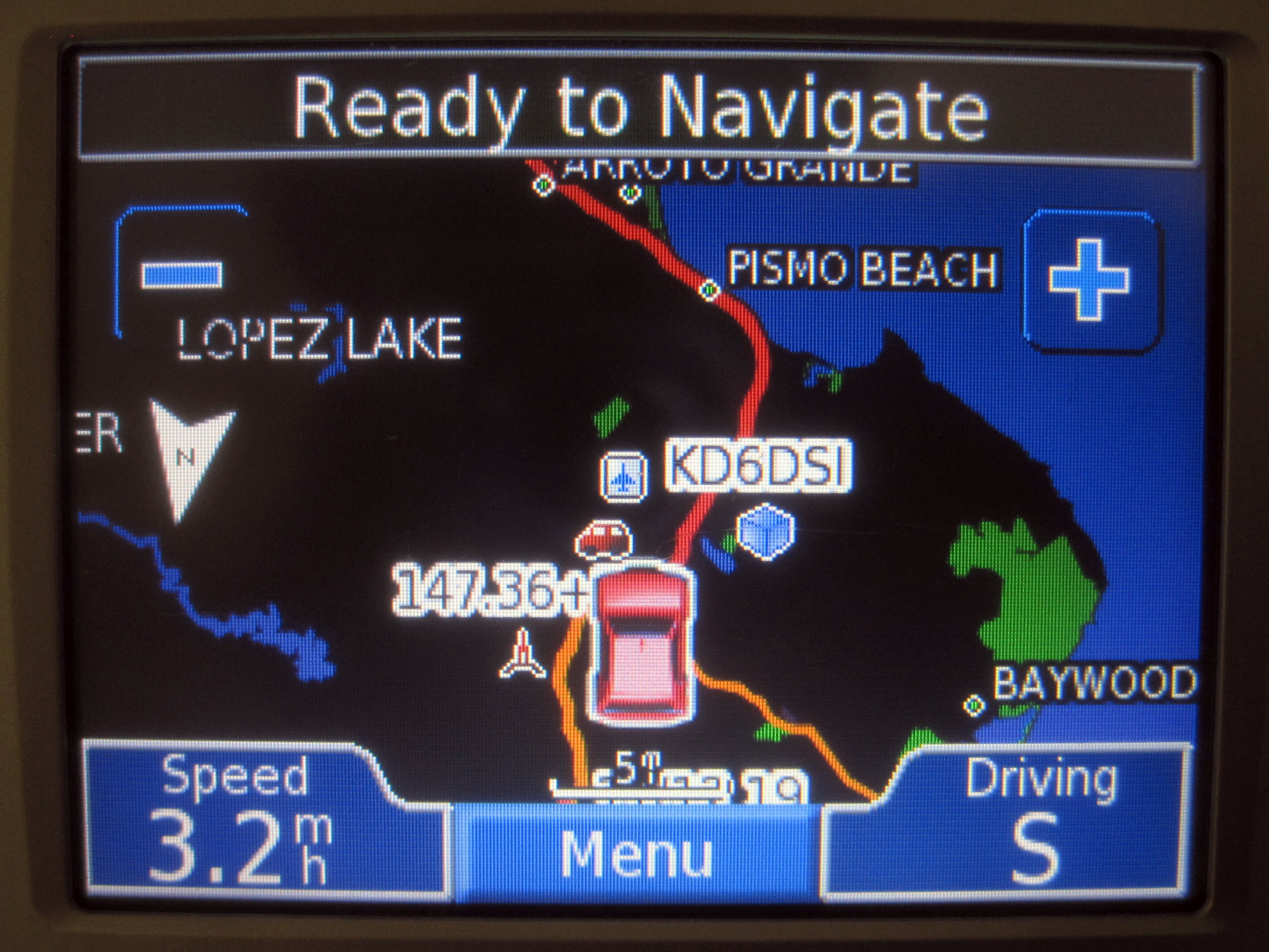
| 23:07, 11 March 2012 | Nuvi 350 - Map View with Objects.JPG (file) |  |
1.35 MB | AI6MS | 1 | |
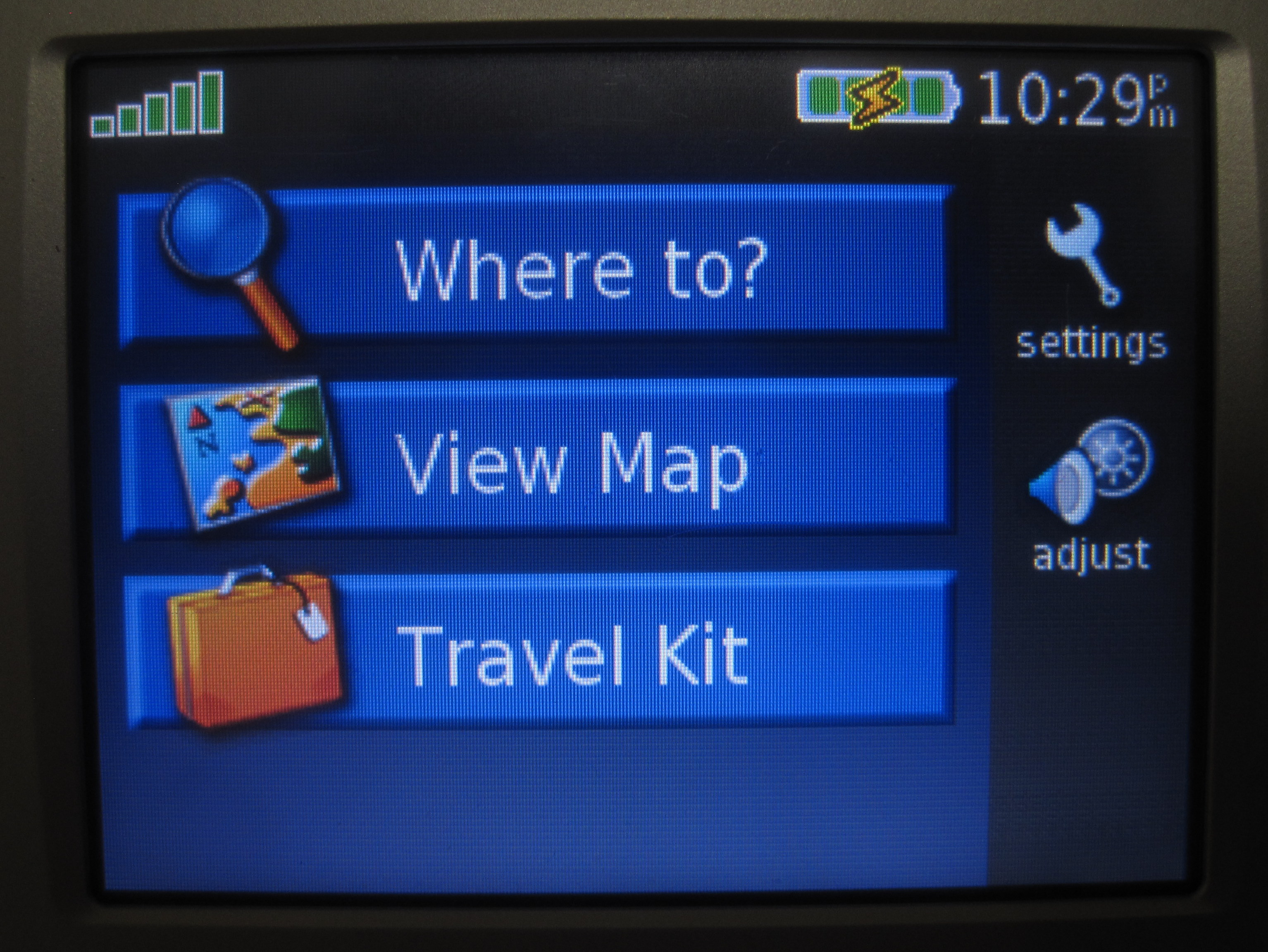
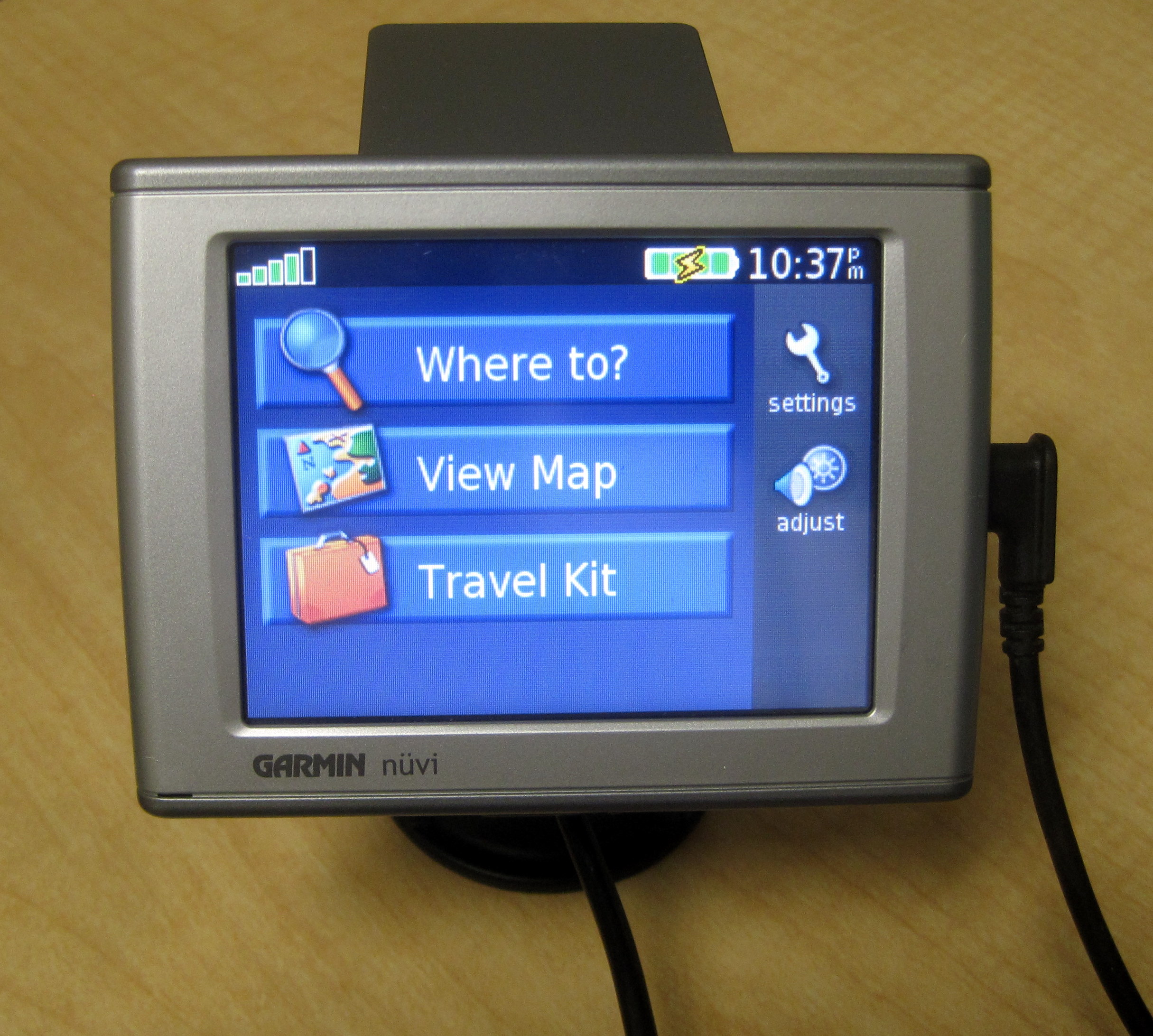
| 23:07, 11 March 2012 | Nuvi 350 - Home Screen.JPG (file) |  |
1.4 MB | AI6MS | 1 | |
| 23:07, 11 March 2012 | Nuvi 350 - Device.JPG (file) |  |
1.01 MB | AI6MS | 1 | |
| 23:07, 11 March 2012 | Nuvi 350 - Favorites Screen.JPG (file) |  |
1.45 MB | AI6MS | 1 | |
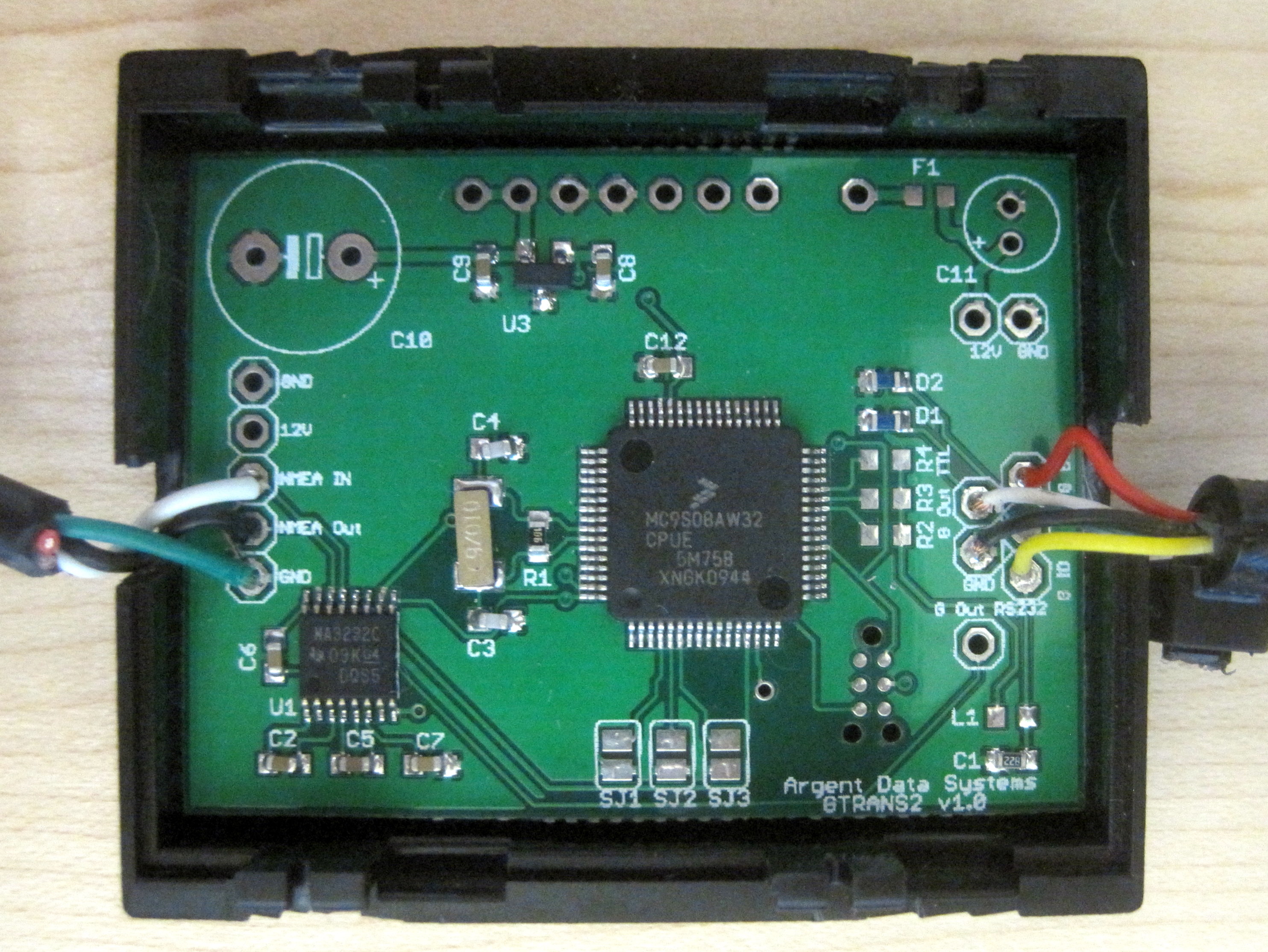
| 23:07, 11 March 2012 | GTRANS - Open Case Detail.JPG (file) |  |
1.32 MB | AI6MS | 1 | |
| 23:07, 11 March 2012 | GTRANS - FTM-350 NMEA Port Detail.JPG (file) |  |
1.09 MB | AI6MS | 1 | |
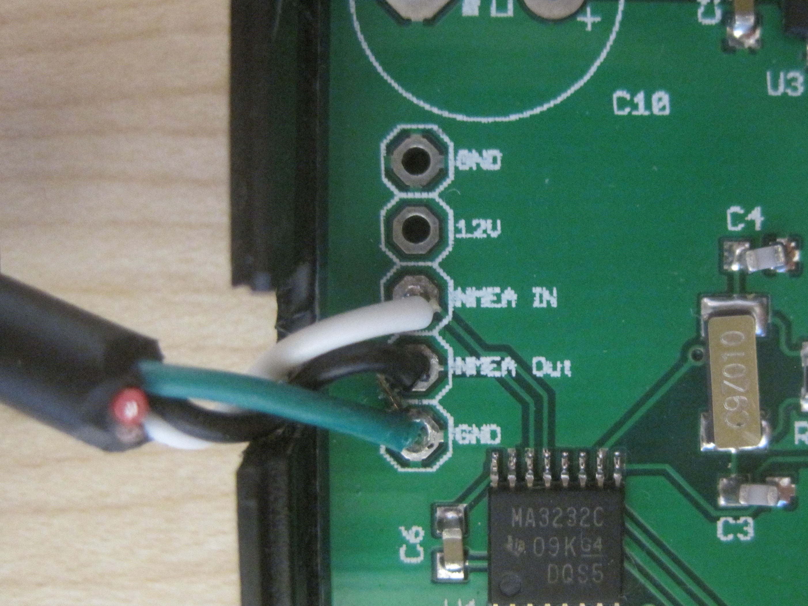
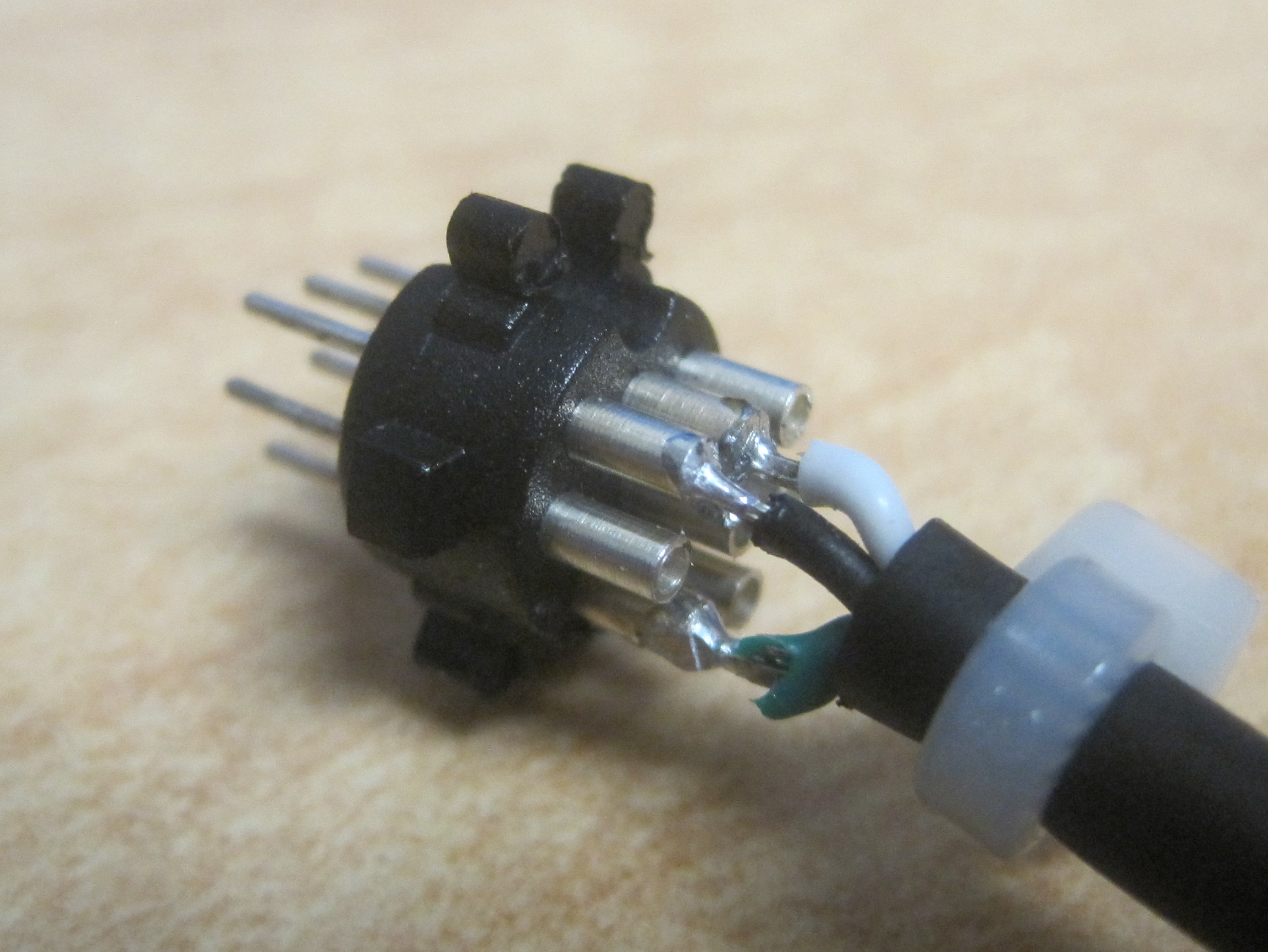
| 23:07, 11 March 2012 | GTRANS - 8-pin mini-DIN Wiring Detail.JPG (file) |  |
508 KB | AI6MS | 1 | |
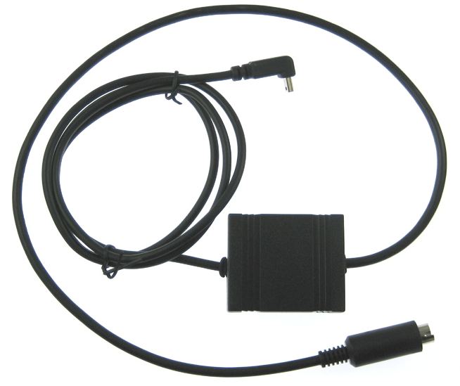
| 23:07, 11 March 2012 | GTRANS - Cable.JPG (file) |  |
40 KB | AI6MS | 1 | |
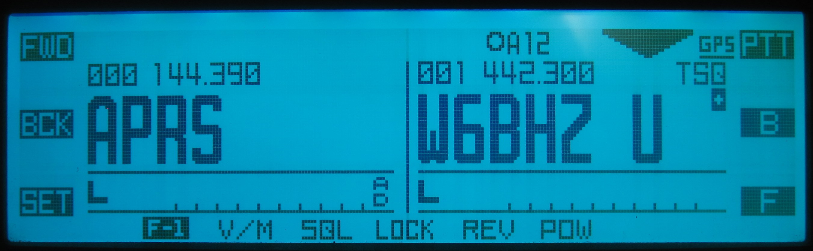
| 23:07, 11 March 2012 | FTM-350 - Setting GPS Screen.JPG (file) |  |
265 KB | AI6MS | 1 | |
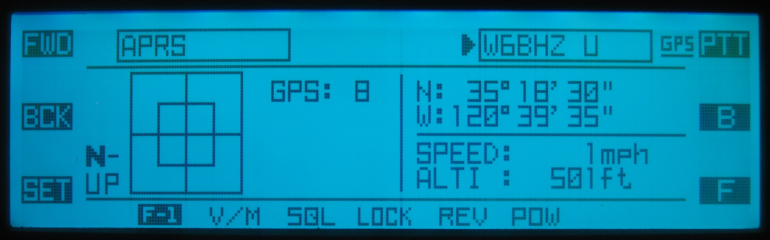
| 23:07, 11 March 2012 | FTM-350 - Setting GPS Indicator.JPG (file) |  |
290 KB | AI6MS | 1 | |
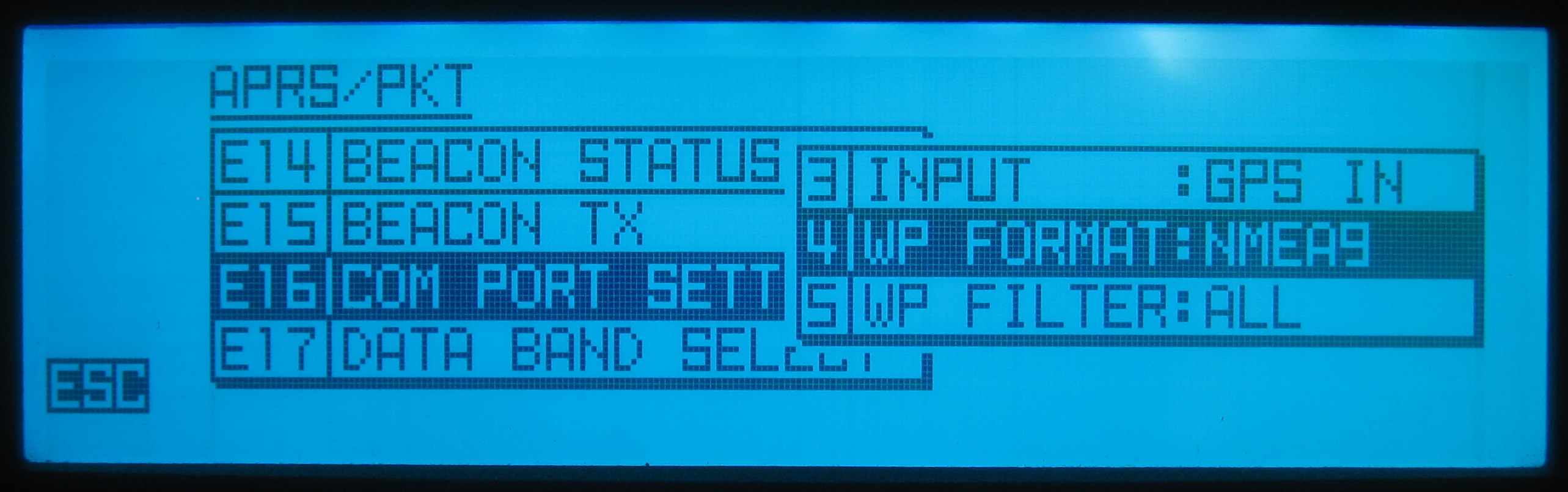
| 23:07, 11 March 2012 | FTM-350 - Setting E16 COM Port Setting 3.JPG (file) |  |
321 KB | AI6MS | 1 | |
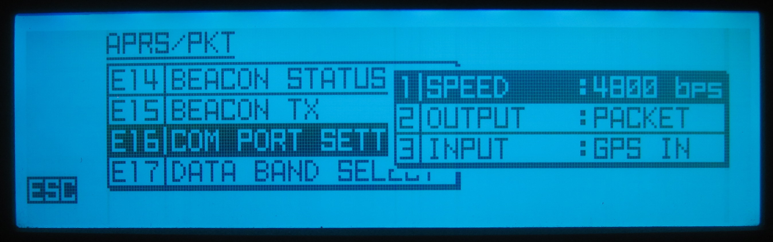
| 23:07, 11 March 2012 | FTM-350 - Setting E16 COM Port Setting 2.JPG (file) |  |
302 KB | AI6MS | 1 | |
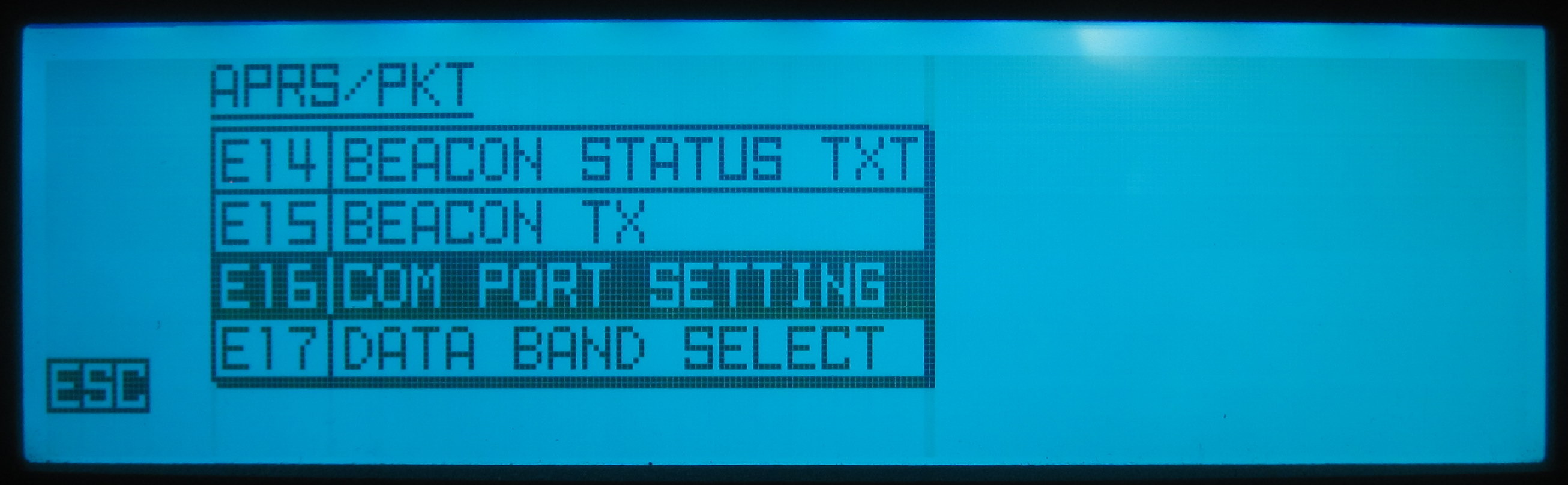
| 23:05, 11 March 2012 | FTM-350 - Setting E16 COM Port Setting 1.JPG (file) |  |
246 KB | AI6MS | 1 | |
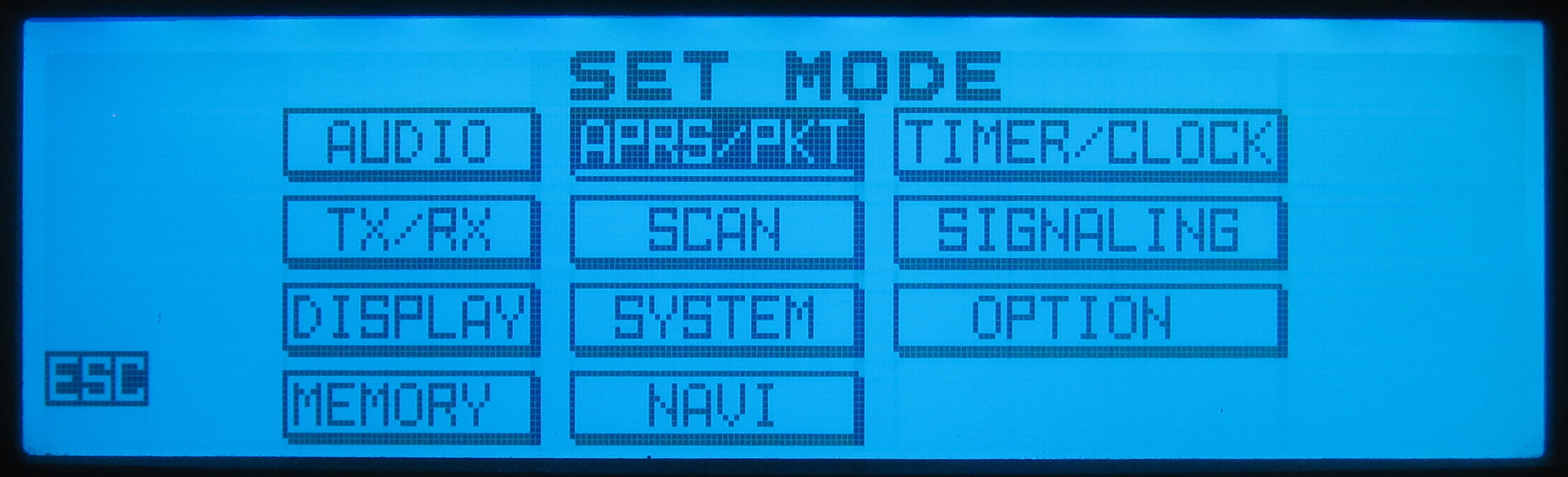
| 23:05, 11 March 2012 | FTM-350 - Setting APRS PKT Menu.JPG (file) |  |
274 KB | AI6MS | 1 | |
| 23:04, 11 March 2012 | FTM-350 - Device.JPG (file) |  |
30 KB | AI6MS | 1 | |
| 23:04, 11 March 2012 | FTM-350 - DATA Port.JPG (file) |  |
1.88 MB | AI6MS | 1 | |
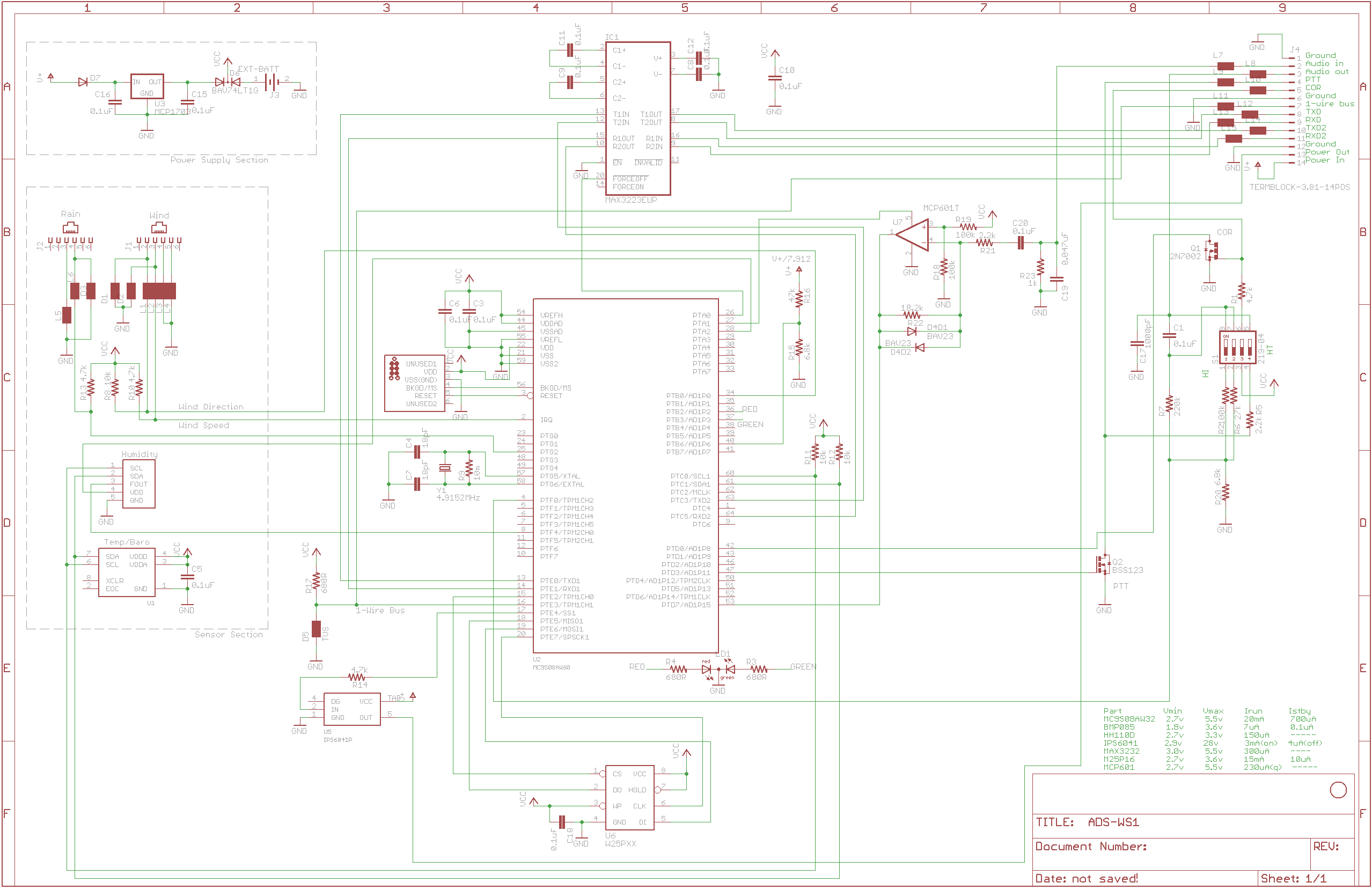
| 13:13, 30 January 2012 | Ads-ws1-16-schematic.png (file) |  |
81 KB | ScottN1VG | ADS-WS1 v1.6 schematic | 1 |
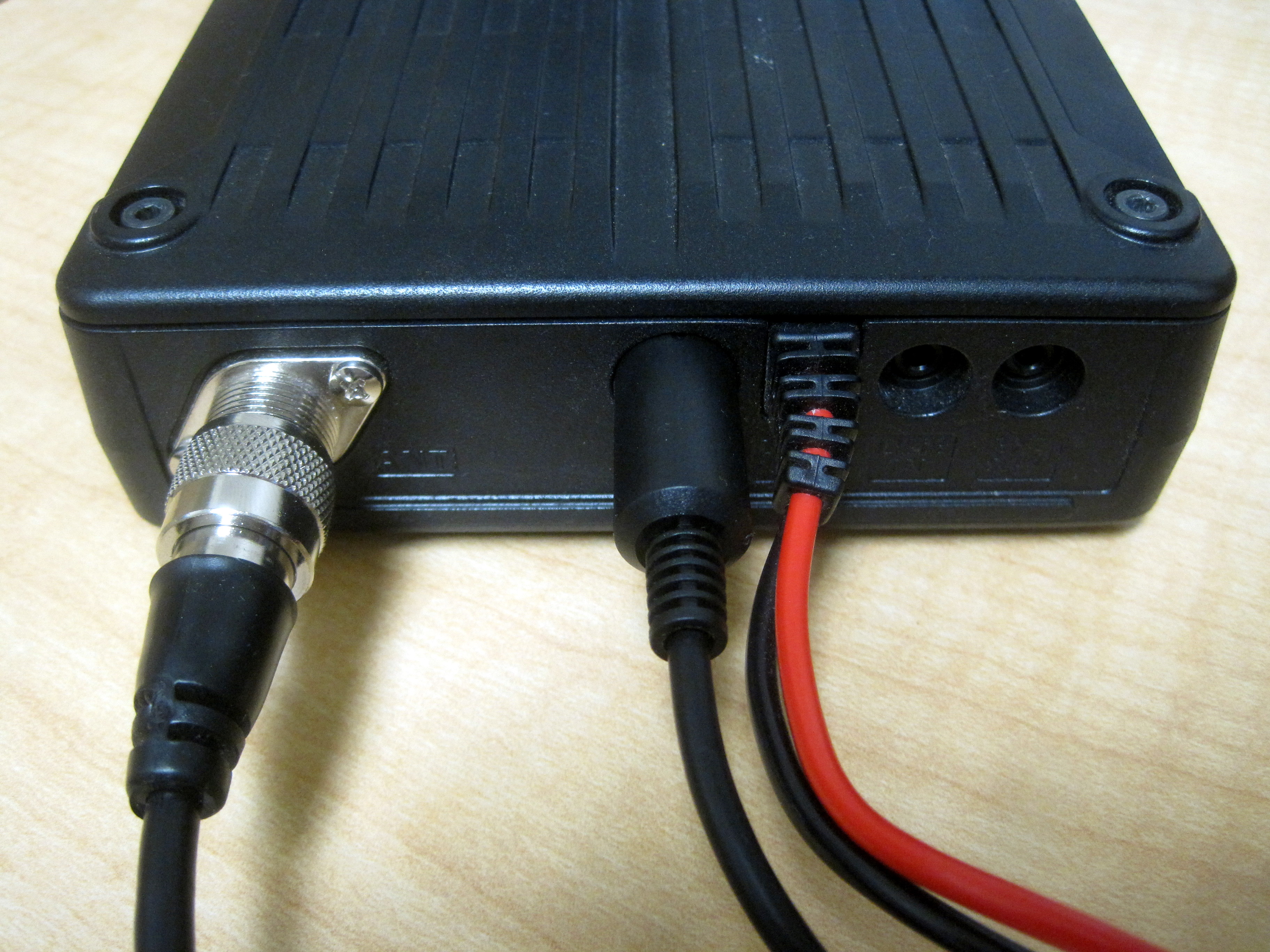
| 12:27, 5 January 2012 | Ot3m-termblk.jpg (file) |  |
586 KB | ScottN1VG | OT3m with terminal block installed | 1 |
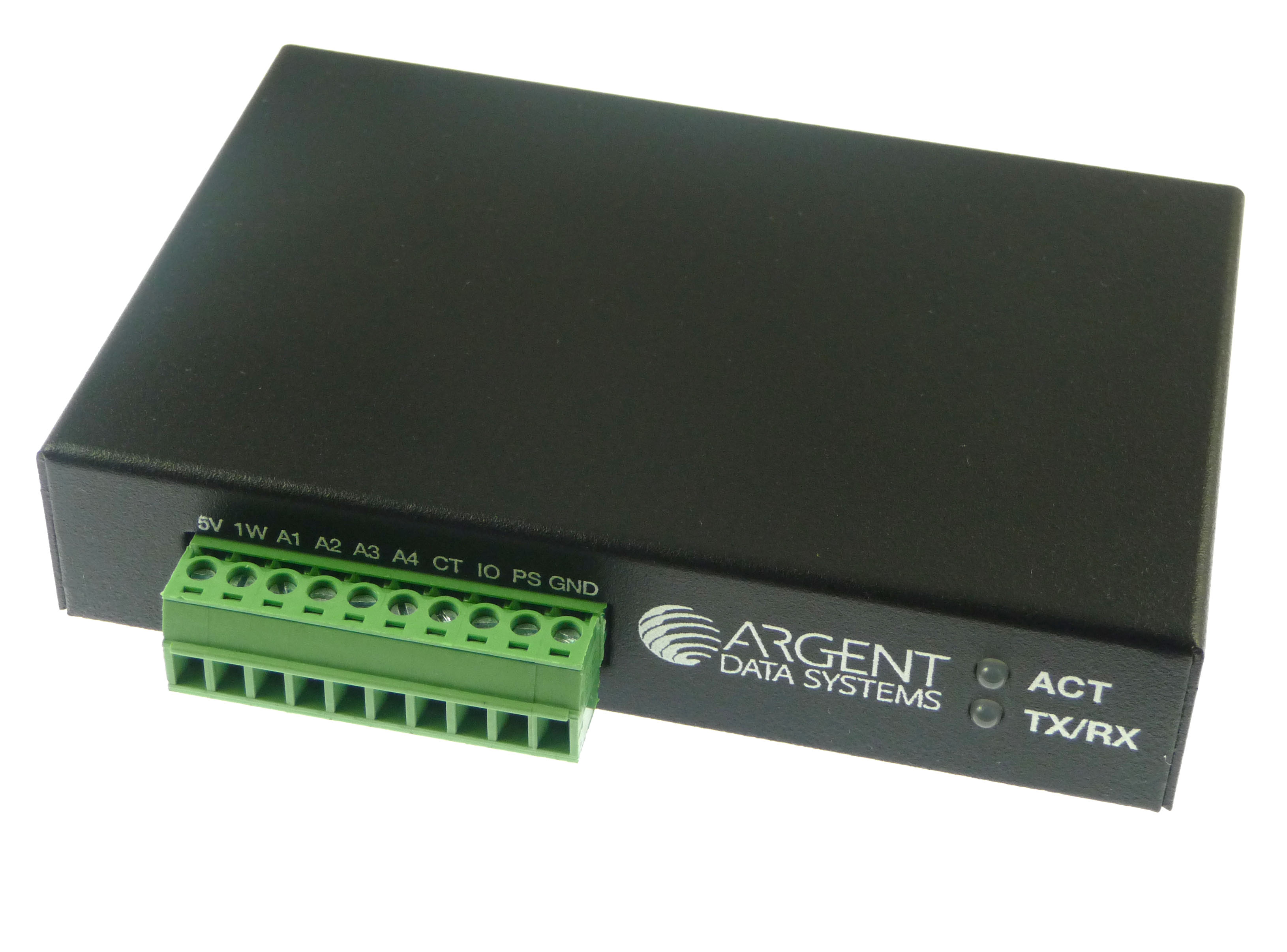
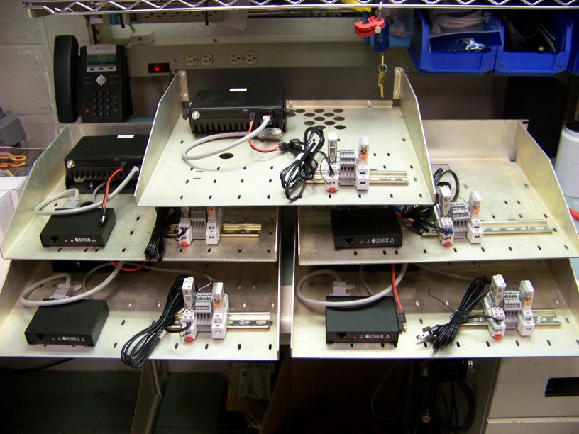
| 21:03, 26 September 2011 | Interface.jpg (file) |  |
101 KB | VE6SRV | Backside I/O connections. | 1 |
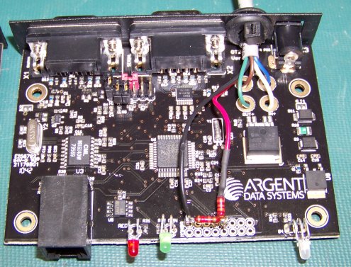
| 19:00, 26 September 2011 | Config.jpg (file) |  |
33 KB | VE6SRV | Configuration input | 1 |
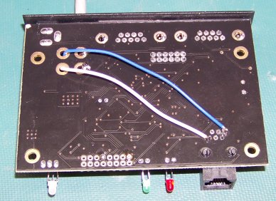
| 18:59, 26 September 2011 | Voltage divider.jpg (file) |  |
70 KB | VE6SRV | Added resistors to create a second voltage divider. | 1 |
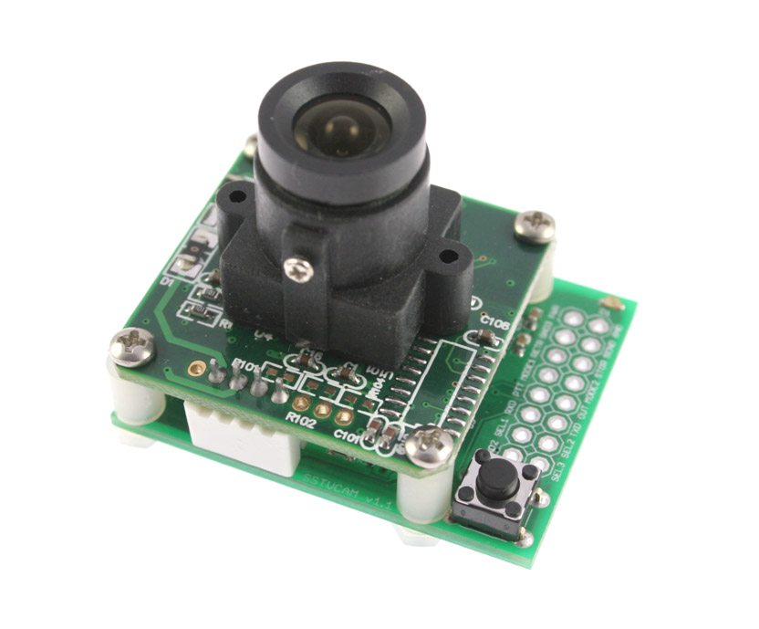
| 13:47, 25 May 2011 | Sstvcam v1.1.jpg (file) |  |
81 KB | ScottN1VG | SSTVCAM v1.1 | 1 |
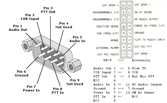
| 19:09, 31 March 2011 | OT2-Moto.png (file) |  |
64 KB | VE6SRV | Changed audio input from pin 2 Ext Mic Audio to pin 5 Flat TX Audio Input. Pin 2 has 500 ohm input impedence, and OT2 is not able to drive the input level high enough to create more than 2 kHz deviation. Pin 5 input impedence is 35K, which OT2 can drive e | 2 |
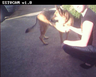
| 16:53, 12 January 2011 | Sstvcam-capture1.jpg (file) |  |
40 KB | ScottN1VG | Sample image capture by SSTVCAM in Scottie 1 mode | 1 |
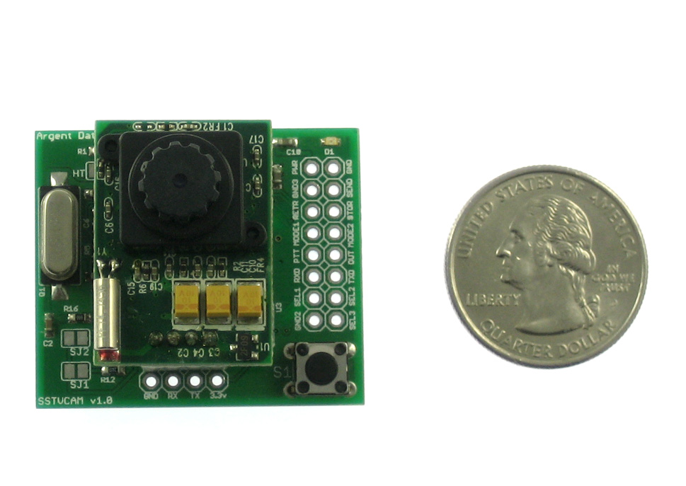
| 16:21, 12 January 2011 | Sstvcam.jpg (file) |  |
148 KB | ScottN1VG | SSTVCAM 1.0 | 1 |
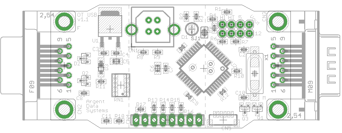
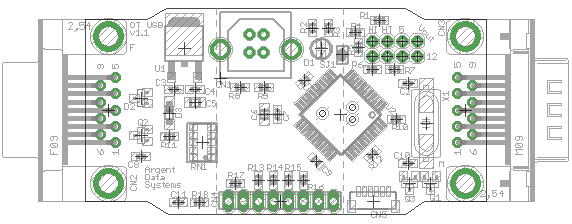
| 21:55, 14 December 2010 | Otusb-layout.png (file) |  |
45 KB | ScottN1VG | OpenTracker USB v1.1 layout | 1 |
| 21:53, 14 December 2010 | Otplus-layout.png (file) |  |
19 KB | ScottN1VG | OpenTracker USB v1.1 board layout | 1 |
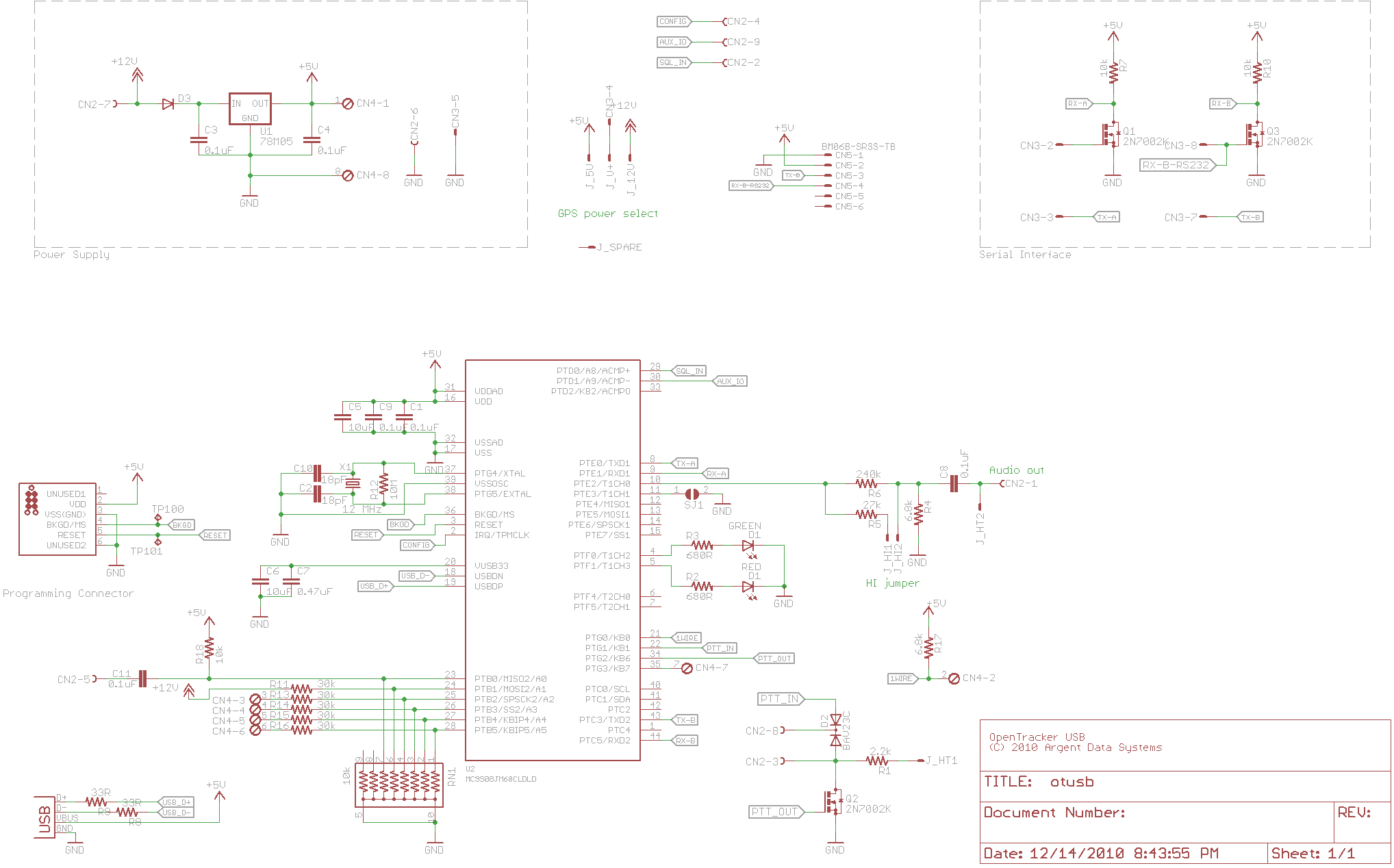
| 21:53, 14 December 2010 | Otusb-schematic.png (file) |  |
57 KB | ScottN1VG | OpenTracker USB v1.1 schematic. Changes from v1.0: Added jumper SJ1 for TTL mode selection Corrected CN5 (GPS connector) pinout | 1 |
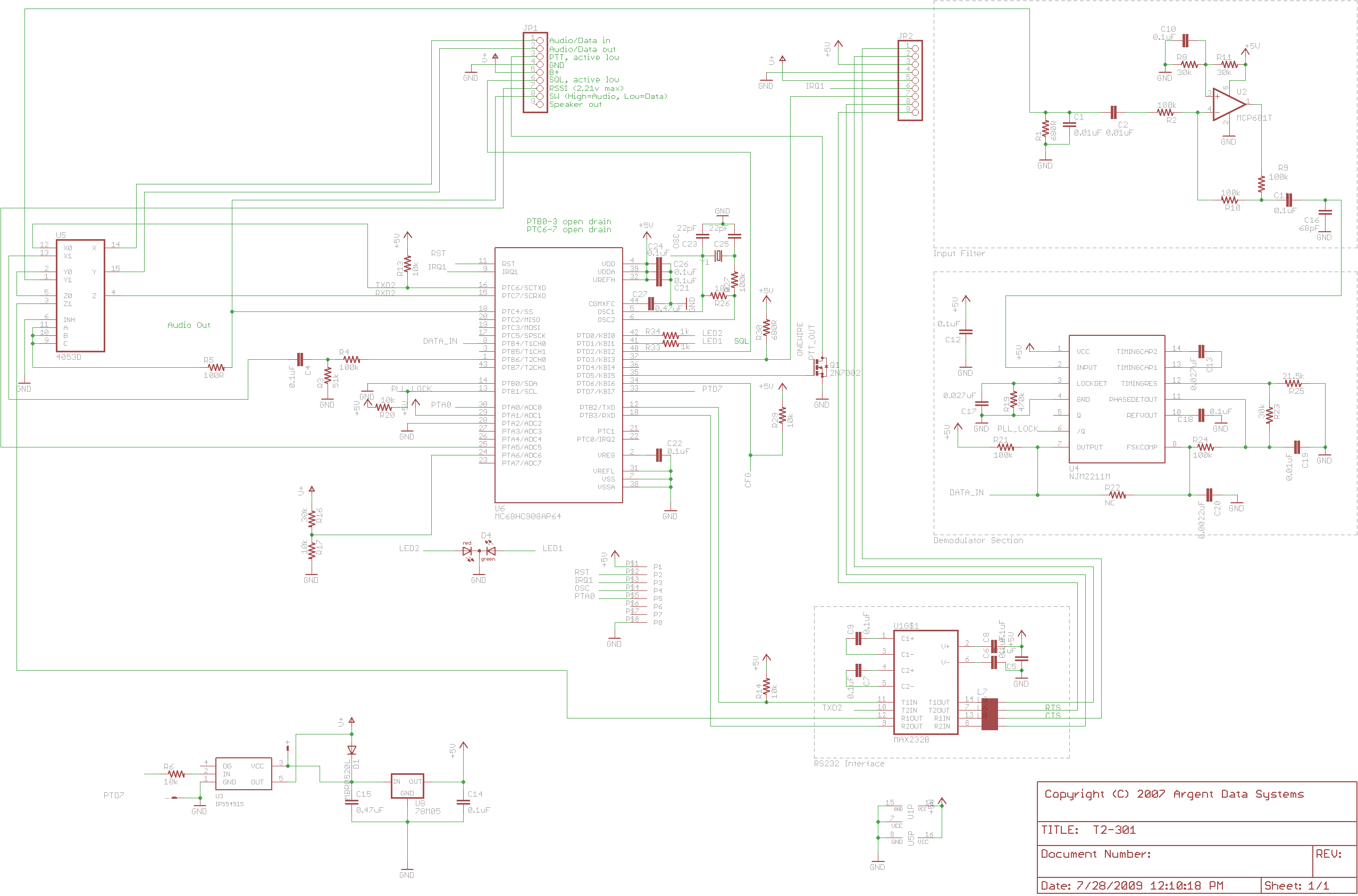
| 12:12, 26 April 2010 | T2-301-schematic.png (file) |  |
77 KB | ScottN1VG | T2-301 v1.1 schematic | 1 |
| 13:48, 12 April 2010 | Radioshield.jpg (file) |  |
93 KB | ScottN1VG | Assembled Radio Shield with Arduino and LCD module | 1 |
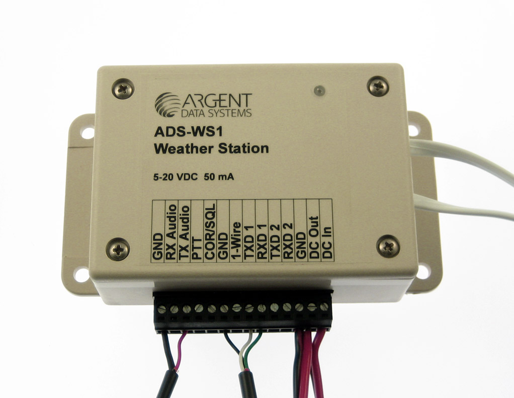
| 11:08, 19 December 2009 | Ads-ws1-rev1.jpg (file) |  |
123 KB | ScottN1VG | ADS-WS1 Weather Station | 1 |
| 11:06, 19 December 2009 | Ws1-side.jpg (file) |  |
365 KB | ScottN1VG | ADS-WS1 Mast | 1 |
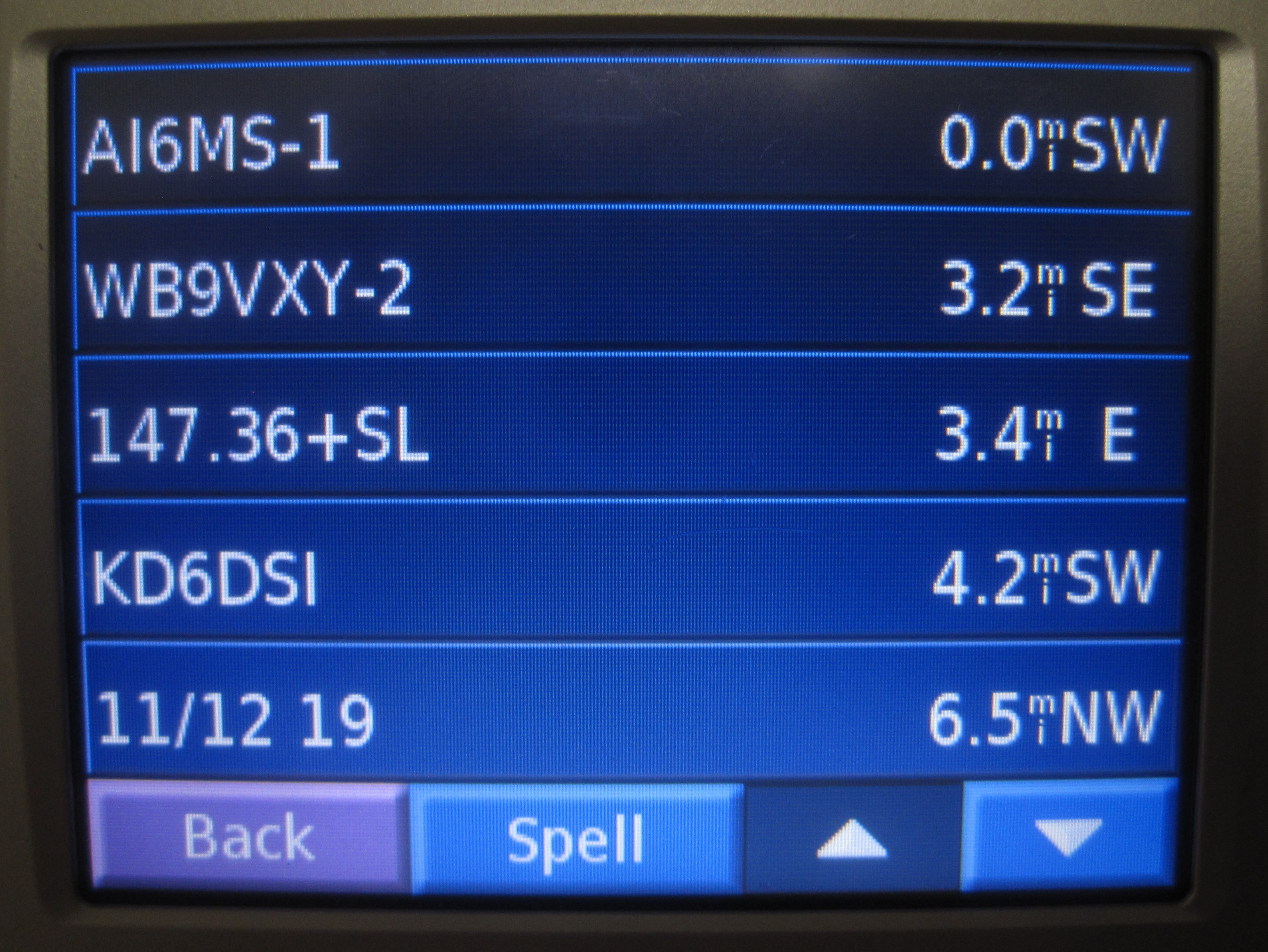
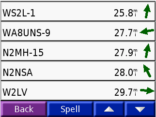
| 07:51, 30 October 2009 | Nuvilist.png (file) |  |
11 KB | VE6SRV | APRS station list on the Nuvi 350 | 1 |
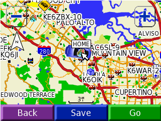
| 07:50, 30 October 2009 | Nuvimap.png (file) |  |
51 KB | VE6SRV | Sample Nuvi Map screen with APRS icons | 1 |
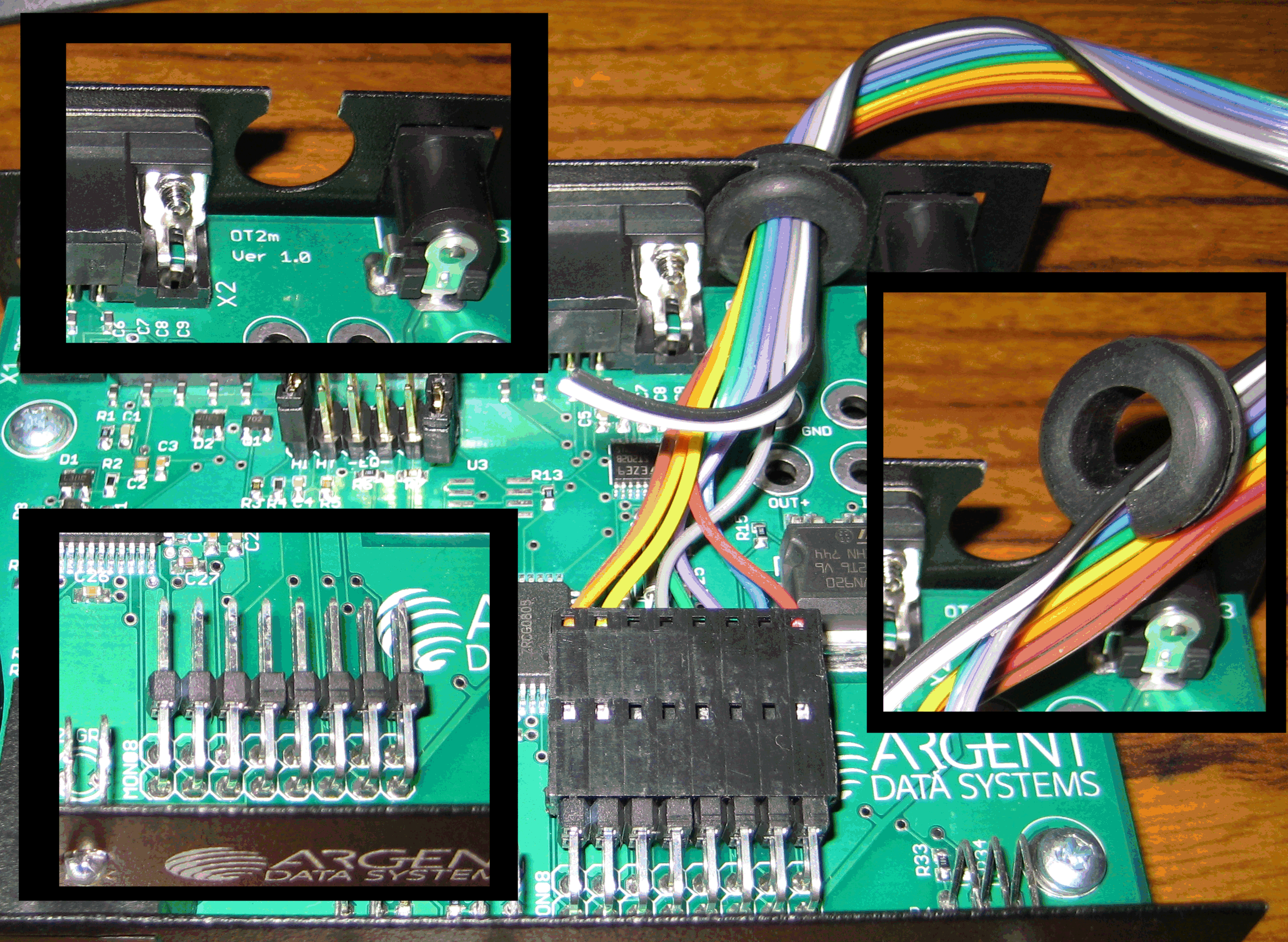
| 05:59, 7 October 2009 | T2 LCD-harness-in-T2-sm.png (file) |  |
1.36 MB | N7FMH | One example of terminating the LCD harness in the T2. | 1 |
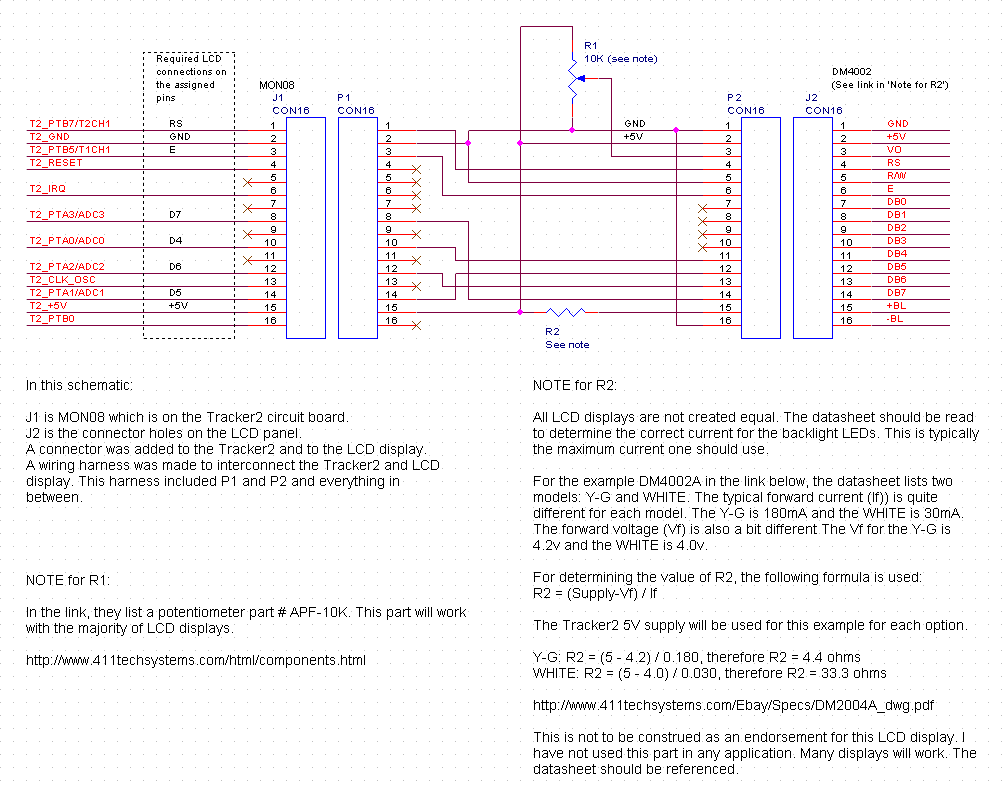
| 10:43, 18 September 2009 | Tracker2-to-LCD-Display.png (file) |  |
30 KB | N7FMH | 1 | |
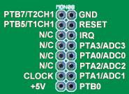
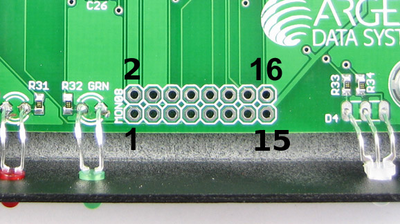
| 13:20, 3 September 2009 | OT2 MON08 pinout.png (file) |  |
26 KB | VE6SRV | OT2 MON08 pinout diagram | 1 |
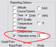
| 11:56, 3 September 2009 | OT2m Reporting Options.png (file) |  |
3 KB | VE6SRV | OT2m Reporting options section from OTWINCFG. | 1 |
| 10:54, 3 September 2009 | OT2 Accessory.png (file) |  |
147 KB | VE6SRV | Accessory port on the front panel of the OT2m. | 1 |
| 09:06, 3 September 2009 | OT2 MON08.png (file) |  |
59 KB | VE6SRV | Close up photo of the MON08 pin header on the OT2m. | 1 |
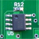
| 08:56, 3 September 2009 | OT2m Voltage Divider.png (file) |  |
38 KB | VE6SRV | Close up of the voltage divider circuit on the OT2m. | 1 |
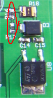
| 08:49, 3 September 2009 | OT2m Temperature Sensor.png (file) |  |
28 KB | VE6SRV | Closeup photo of the LM335D temperature sensor chip used on the OT2m. | 1 |
| 00:37, 26 June 2009 | Ot2m-mon08.jpg (file) |  |
83 KB | Oh7lzb | OT2m MON08 programming header with pin markings | 2 |
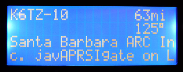
| 12:55, 16 June 2009 | T2-20x4.jpg (file) |  |
58 KB | ScottN1VG | Tracker2 LCD display | 1 |
First page |
Previous page |
Next page |
Last page |