OpenTracker+
You can browse the OpenTracker+ source code at Freepository or retrieve it using SVN with the username and password 'guest'. The free special edition version of CodeWarrior for Microcontrollers can be used to compile the source code. The .s19 file generated by CodeWarrior can be uploaded to the tracker using otwincfg.exe.
Contents
OpenTracker+
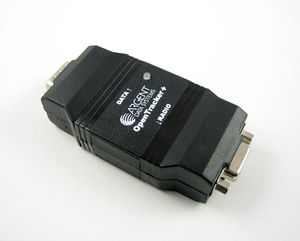
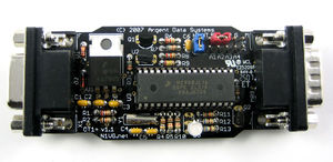
The OpenTracker+ is the second generation of OpenTracker that Argent Data produced. It is a single through-hole board with two DB9 ports on it, one for programming and GPS data in, and the other port for radio connection.
Features include: - 1200,300, and PSK31 transmit of APRS protocol data. - Encode and transmit data from several supported weather stations. - Report temperature and voltage from on-board sensors - Outputs waypoint data for display on various external devices
The firmware is programmable via the OTWINCFG program. The unit does not print all recived packets, although it does decode it for efficient channel usage.
The OpenTracker+ has a single port for computer or GPS connection. The OpenTracker2 has two ports for GPS/computer.
OpenTracker+ SMT
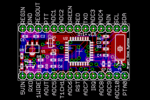
The Opentracker + SMT is a 28-pin board that fits into a stanard IC socket. The board consists of a Freescale HC908JL16 processor and a regulator. No LEDs are included on the board. The board accepts ether 5V directly to the Vcc pin, or 6-28V through the regulator. Max current draw (during xmit) is on the order of 28ma.
Note that the on-board regulator (an 78L05UA) may not be able to provide enough current to power the OT1+ SMT and a GPS.
The OTWINCFG program is used to program the board, and the custom software specifically used for this board configures 8 pins to read A/D information and report it in the telemetry APRS packet that is transmitted.
The analog values transmitted with this firmware version correspond to pins ADC1 through ADC5. In the binary section of the APRS telemetry packet, the leftmost two bits are set to '00' and the rest report the states of pins T1CH1 and ADC6 through ADC9, in that order.
Opentracker+ RT
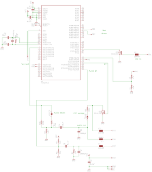
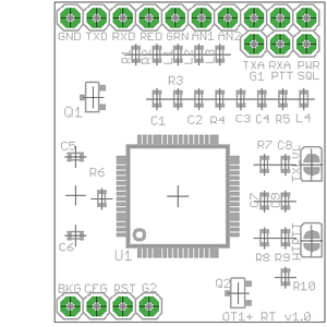
The OpenTracker+ RT is a modified version of the OT1+ based on the MC9S08AW32 processor. The RT board was designed to meet the needs of a small number of commercial AVL customers. Changes include the ability to function from a 3.3 volt supply, an automatic low-power shutdown mode, and logging of previous positions for automatic retries. The RT is currently in limited production. Source code has not been published yet.
Radio Port Pinouts
| Pin | Function |
|---|---|
| 1 | Audio Out |
| 2 | COR / Squelch Input |
| 3 | PTT Output |
| 4 | Counter / Transmit Now Input |
| 5 | Audio Input |
| 6 | Ground |
| 7 | Power Input |
| 8 | PTT Input |
| 9 | ADC5 Input / Power Relay |
Serial Port Pinouts
| Pin | Function |
|---|---|
| 1 | No Connection |
| 2 | Data In (RS-232) |
| 3 | Data Out (RS-232) |
| 4 | Power Out |
| 5 | Ground |
| 6 | No Connection |
| 7 | 1-Wire Data Bus |
| 8 | No Connection |
| 9 | No Connection |
The OT1+'s data port (X2) is wired to allow connection to a GPS receiver using a standard cable. A null modem cable is required for connection to a computer. When wiring your own null modem cable, swap pins 2 and 3 (pin 2 on the PC connects to pin 3 on the tracker and vice versa) and wire pin 5 straight through. No other connections are required for programming.
COR / Squelch Input
This input is active high unless the ‘Invert CD’ option is selected in software. Do not exceed 5 volts at this input.
Counter / Transmit Now Input
The function of this input depends on whether the counter option is enabled. If the counter is enabled, pulling this pin to ground increments the counter. Otherwise, grounding this pin causes an immediate transmission, assuming the tracker is in a state in which it can transmit. If this input is connected with a long cable or may be subjected to RFI, you may need to provide a stronger pull-up to 5 volts. A 10k or 4.7k resistor is usually suitable. See also the ‘jumper’ setting in the profile switching menu for additional uses.
PTT Input
Active low, used for mic encoder operation.
1-Wire Data Bus
Bidirectional data interface using the Dallas Semiconductor 1-Wire scheme. This is used primarily for interfacing with the Dallas / AAG TAI-8515 weather station. It may also be used with standalone sensors such as the DS18S20.
Data Out
This signal varies from 0 to 5 volts and is compatible with most RS-232 devices. However, some GPS receivers and weather stations require a negative voltage to communicate properly and will require an external level shifter.
OpenTracker+ Setup and Operation
The following general steps are required to use your assembled OpenTracker+:
- Build or obtain cable for connection to radio and power
- Connect tracker to computer, radio, and power
- Run configuration program to set callsign and audio level
- Disconnect computer and connect GPS receiver or weather station
The radio connector, X1, is similar to that used by the Kantronics KPC-3 and the Byonics TinyTrak3. Any cable that was made to interface a radio to either of these devices should work with the OpenTracker+. Pre-assembled cables may also be purchased from RPC Electronics at http://www.rpc-electronics.com.
Most handheld radios (with the notable exception of those made by Kenwood) assert PTT by grounding the microphone input through a resistor. The OpenTracker+ uses this method if the ‘HT’ jumper is installed. This jumper should be omitted when the tracker is used with mobile radios or with handhelds that do not use this method of PTT keying.
The OpenTracker+ requires 6.7 to 28 volts DC. However, the maximum voltage that can be measured and reported by the tracker is 18.5 volts.
Power may be supplied through either 9-pin connector. Most often, it is supplied through pin 7 of the radio connector. It may also be supplied through pin 4 of the data connector if a jumper is installed in the ‘12’ position of the header marked ’12 - 5’.
Receive Adjustment
The OpenTracker+ can be set to detect any signal on its audio input (including voice, data, and static) or only valid data. The latter mode is referred to as Data Carrier Detect, or DCD. If DCD is enabled, the radio may be operated in open-squelch mode, but the tracker will detect only data signals and not voice. All receive settings are made through the configuration program.
Transmit Adjustment
The OpenTracker+ has two audio level ranges. The higher range is selected by installing a jumper in the ‘HI’ position on header block JP1. If you’re not sure which range your radio requires, start with the low range and install the jumper only if you’re unable to produce a suitable modulation level.
The audio level may be fine-tuned through the configuration program. The configuration program can also be used to transmit tones for calibration.
If you have a deviation meter or service monitor available, set the transmit level to achieve a maximum deviation of about 3.2 kHz for VHF FM 1200 baud operation. If you aren’t able to directly measure the deviation, use another radio to listen to the transmitted audio. Increase the level slowly until the signal doesn’t get any louder, and then turn it back down until it gets noticeably quieter, and turn it down a few notches below that. Proper audio level is critical to ensuring the transmitted packets can be received and decoded. A transmit audio level set too high will cause clipping in the transmitter, which results in signals that are difficult or impossible to decode.
LED Blink Codes
The tracker reports its status through the use of a multi-color LED as follows:
| Action | Meaning |
|---|---|
| Rapid green blinking | Channel is in use |
| Single green flash | Received valid GPS fix |
| Double red flash | Received invalid GPS fix, GPS may not be ready |
| Solid red | Transmitting or in configuration mode |
| Single yellow flash | A position was received and decoded |
Firmware Revision History
Build 54896
06 March 2009 - Fixed profile switching on ADC input and changed fifth telemetry value to X1-9 input to match manual.
