Telemetry
Some of the telemetry information can be embedded into the comment section of a packet, or you can configure the tracker to send separate packets in the APRS telemetry defined format.
T#sss,aaa,bbb,ccc,ddd,eee,76543210
"sss" is a sequence number which increments upon each telemetry report sent, wrapping at 999 back to 000. "aaa,bbb..." are analog values between 0 and 255. Their conversions are given in the table below. 0-7 are are binary bits, either 0 or 1. The currently active configuration profile may be reported as a telemetry bit.
A digital counter input is available on some tracker models. The counter value can be reported in status packets and in some models as a telemetry value.
For some models, the commands ANALOG and GPIO can be used to read specified analog inputs and read or set general-purpose digital I/O pins. The pin assignments for these commands are shown below.
Contents
Pin Assignments by Device
This information reflects current firmware versions and production hardware. Beta hardware and older firmware versions may have different assignments.
OT3m
| Pin | Function | Value |
|---|---|---|
| Supply Voltage | Telemetry aaa, ANALOG 0 | Volts * 10 (Max 20v) |
| Terminal Block A1 | Telemetry bbb, ANALOG 1 | Volts * 10 (Max 20v) |
| Terminal Block A2 | Telemetry ccc, ANALOG 2 | Volts * 10 (Max 20v) |
| Terminal Block A3 | Telemetry ddd, ANALOG 3 | Volts * 10 (Max 20v) |
| Terminal Block A4 | Telemetry eee, ANALOG 4 | Volts * 10 (Max 20v) |
| Radio Pin 9 (AUX_IO) | GPIO 0 | ON = High, OFF = Low |
| Terminal Block IO | Telemetry bit 1, GPIO 1, Profile Jumper | ON = High, OFF = Low |
| Terminal Block CT | Counter Input (if enabled) or Beacon Trigger | Pull to ground to activate |
| Active Profile | Telemetry bit 0 | ON = Profile 2, OFF = Profile 1 |
OpenTracker USB
| Pin | Function | Value |
|---|---|---|
| Supply Voltage | Telemetry aaa, ANALOG 0 | Volts * 10 (Max 20v) |
| CN4 Pin 3 | Telemetry bbb, ANALOG 1 | Volts * 10 (Max 20v) |
| CN4 Pin 4 | Telemetry ccc, ANALOG 2 | Volts * 10 (Max 20v) |
| CN4 Pin 5 | Telemetry ddd, ANALOG 3 | Volts * 10 (Max 20v) |
| CN4 Pin 6 | Telemetry eee, ANALOG 4 | Volts * 10 (Max 20v) |
| Radio Pin 9 (AUX_IO) | GPIO 0, Power Relay | ON = High, OFF = Low |
| CN4 Pin 7 | Telemetry bit 1, GPIO 1, Profile Jumper | ON = High, OFF = Low |
| Active Profile | Telemetry bit 0 | ON = Profile 2, OFF = Profile 1 |
OT2m Telemetry elements
| Entry # | Description | Sensor input |
|---|---|---|
| aaa | Temperature as reported by an on board LM335D sensor. (U5) | |
| bbb | Source voltage being provided to the OT2m, measured by a voltage divider. (R16 / R17) | |
| ccc | Read from pin 10 (PTA0/ADC0) on the MON08 header on the circuit board. Allowable voltage input range is between 0 and 5 volts. | |
| ddd | Counter value, with the counter input on pin 1 (IRQ1) of the accessory port, also available from pin 6 (IRQ/counter/transmit-now input) on the MON08 header on the circuit board. Counter can be incremented by grounding this input. Software debounce settings are available. | |
| eee | HDOP value reported by an attached GPS. | |
| xxxxxxxx | Only the last 2 binary bits are used on the OT2m.
Bit 7 reports the current status of the jumper input located on pin 6 (CFG) of the accessory port. Grounding this input reports a bit state of 1. Bit 8 reports the current profile in use. |
T3-301 Telemetry elements (UNDER CONSTRUCTION)
| Entry # | Description | Sensor input |
|---|---|---|
| aaa | ||
| bbb | ||
| ccc | ||
| ddd | ||
| eee | ||
| xxxxxxxx |
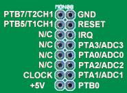
MON08 pinout
1 - PTB7/T2CH1 (digital I/O or timer channel) 2 - GND 3 - PTB5/T1CH1 4 - Reset 5 - No connection 6 - IRQ (counter/transmit-now input) 7 - No connection 8 - PTA3/ADC3 (digital I/O or ADC input) 9 - No connection 10 - PTA0/ADC0 11 - No connection 12 - PTA2/ADC2 13 - Clock oscillator (32.768 kHz) 14 - PTA1/ADC1 15 - +5V 16 - PTB0 (digital I/O) |
Telemetry Equations, Units, Parameters, and Labels
APRS telemetry reports contain only raw values, and it is up to the user interface software to display the information in a human readable format, with appropriate calculations performed to provide corrected values.
In order to do this, the software needs to have some information provided to it so that it can do the appropriate conversions, display each value with the required units, properly labelled.
There are 4 sentences that provide this required information.
- A Parameter Name message.
PARM.Temp.,Bat.,Extrn,Count,HDOP,NA,NA,NA,NA,NA,NA,JU,CF
The original DosAPRS program was limited to 80 characters per line, and to fit those limits, arbitrary parameter name lengths were chosen. If you wish to stay compatible with DosAPRS, the paramater name lengths for the 5 analog channels are 7, 6, 5, 5 and 4 characters. The lengths for the 8 digital bits are 5, 4, 3, 3, 3, 2, 2, and 2 characters respectively.
- A Unit/Label message.
UNIT.Deg.,Volts,Volts,NUM,HDOP,,,,,,,ON,NUM
Sets the labels associated with the analog values, and for the digital bits, a label to association with the digital state.
- An Equation Coefficients message.
EQNS.0,1.9608,-273,0,0.07843,0,0,0.07843,0,0,1,0,0,0,0
There are three coefficients for each analog channel, a,b,and c. These three coefficients get plugged into a quadratic equation along with the reported analog value x. The result is calculated from this equation where FINAL VALUE = a*x^2 + b*x + c
- A Bit Sense/Project Name message.
BITS.11111111,Your Telemetry Name
BITS format specifies which bit state is associated with the label. You can also specify a title for your telemetry page.
APRS telemetry definition sentences simply need to be sent to the target callsign as an APRS message.


