SpinFx Phoenix Hoop
In July 2018, Argent Data Systems took over support of the SpinFx Phoenix smart hoop. The 2018 Hyperion Phoenix represents a complete redesign using Argent's own Hyperion technology. Official support for legacy SpinFx hoops is ending, and the purpose of this page is to provide repair and service information for Phoenix hoop owners and independent repair shops working with the Phoenix.
Contents
Basic Phoenix Troubleshooting
Internal Reset
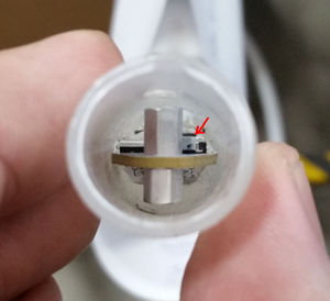
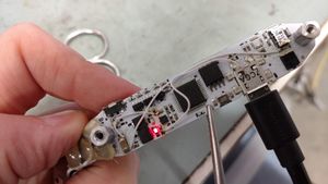
Open up the hoop tubing/connector and locate the internal reset button. It's a tiny gray button on the circuit board next to the metal standoffs. Press the button GENTLY for 5-10 seconds using a blunt object like a paperclip or hair pin. If it works, you should see the green LED light up, and your hoop should restart.
Bootloader Mode
Phoenix hoops may sometimes get stuck in bootloader mode, which will cause them to stop lighting up but still respond to a computer over USB. Fortunately this can often be fixed by simply updating the firmware. Make sure you charge the hoop for a bit before trying this, as it needs a little power to work.
1. Download the firmware updater from the Spin FX website: http://www.spin-fx.com/support/firmware-updater/
2. Open up the firmware updater, plug in your hoop, turn on the hoop (press power button, even if it doesn't appear to respond).
3. Go to Options, and then go into Advanced mode.
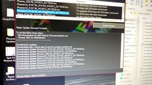
4. Select the firmware version for your hoop and hit the Update Firmware button. The firmware version is going to be generally based on the color of your hoop's circuit board (white, green or black) - check the Description.
If it works, the updater will tell you when it's done updating. The hoop should be fixed now if it was actually in bootloader mode. If the updater just says "waiting for hoop...", or the hoop still won't light up, then you're out of luck.
Phoenix hoops may also be forced into bootloader mode by shorting the 'BOOT' jumper on the circuit board. To do this, you'll need to remove the hoop guts from the tubing.
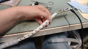
Remove screw and plastic rivet from tubing. Rivets usually get destroyed during removal, so you'll want to have spares (search for 1/8” plastic push-in rivets). Pull guts out of hoop until you can access circuit board. Plug into computer.
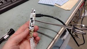
Attach metal tweezers or forceps across the two solder pads (tiny silver squares) indicated below. The goal is to let an electrical current flow between the two pads. Try to keep your tweezers from contacting other metal parts on the circuit board. It's ok if they touch the backing of the board (white/gray background, in this case).
Fire up the Spin FX Firmware Updater on your computer. Press the internal reset button on your hoop's circuit board for 5 seconds. (See pages 18-19 of Spin FX manual for pics of reset button.) If your hoop is in bootloader mode, the Firmware Updater will now say “Device Status: BOOTLOADER” at the bottom.
Go to Options, and then go into Advanced mode. Select the firmware version for your hoop and hit the Update Firmware button. The firmware version is going to be generally based on the color of your hoop's circuit board (white, green or black) - check the Description.
If it works, the updater will tell you when it's done updating. The hoop should be able to restart now if it was actually in bootloader mode.
If the updater just says "waiting for hoop...", or the hoop still won't light up, then you're out of luck. Reach out to us for help.
2016 Phoenix PCB modifications
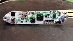
The 2016 Phoenix PCB is white and is marked Phoenix_r130 in the lower right corner of the bottom side of the board. This is a 4-layer PCB. Many common failures of this board are due to burned-out internal traces. Some of these can be prevented or fixed by adding wires as shown.
The most difficult of these, and unfortunately the most commonly needed, is the connection from the USB connector's +5V pin (the rightmost of the 5 pins) to R6. This carries the USB supply current to the battery charger IC. A hot air rework station or a very fine soldering iron tip is needed to attach the wire to the USB port.
Capacitor failures
The multilayer ceramic capacitors on the board can fail due to flexing or shock. They will typically fail short. In some cases this failure can be catastrophic and will result in visible damage to the capacitor, PCB, or surrounding components. Shorted PCBs are often not repairable. See below for a replacement board.
Check the capacitors with an ohm meter. If the 3.3v bus is shorted to ground, begin by removing capacitors with a hot air rework gun until the short is cleared. Discard and replace damaged capacitors. We recommend replacing with board flex tolerant parts like TDK's C1608X5R1A475K080AE.
LED Power Control MOSFETs
Power transistors Q1 and Q2 on the 2016 board were specified as Infineon p/n BSZ120P03NS3 G. This part is not well-suited to this application and has a very high on-state resistance at the gate voltage used. If this part needs to be replaced, it should be replaced with a more suitable component like Toshiba's TPN4R712MD,L1Q. Only a single replacement MOSFET is needed and the other position may be left empty after the Toshiba part has been installed. Heat dissipation is reduced considerably and current handling is improved.
Replacement PCB
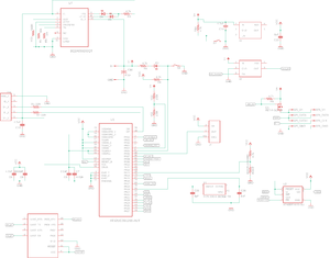
A new 4-layer PCB was developed to replace the 2016 Phoenix board while keeping most of the same components. This is not a feature enhancement, but only corrects some design problems with the earlier boards and replaces some of the more problematic components. Bare PCBs may be ordered directly from OSH Park.
MOSFETs Q1 and Q2 are replaced with a single Toshiba SSM3J328R,LF and the charger IC is replaced with a Texas Instruments BQ24090DGQT.
2016 Phoenix r130 Bill of Materials
| Designator | Part Number | Description |
| BT | HM-13 | Bluetooth module |
| C1,C2 | Murata GRM155R71C104KA88D | 0.1uF 0402 capacitor |
| C9 | Murata GRM155R60J102KA01D | 1000pF 0402 capacitor |
| R11,R12 | KOA RK73H1ETTP1002F | 10k ohm 0402 resistor |
| R13 | Yageo RC0402JR-071KL | 1k ohm 0402 resistor |
| C15 | Murata GRM155R61A105KE01D | 1uF 0402 capacitor |
| C6 | Murata GRM155R61A225KE95D | 2.2uF 0402 capacitor |
| R1,R2 | Panasonic ERJ-2GEJ390X | 39 ohm 0402 resistor |
| R3,R4,R6,R8,R9,R14 | KOA RK73B1ETTP472J | 4.7k ohm 0402 resistor |
| C3, C8, C14, C18, C19 | Murata GRM155R60J475ME87D | 4.7uF 0402 capacitor (not recommended) |
| C7 | TDK CGA2B2X7R1H471K050BA | 470pF 0402 capacitor |
| C10 | Yageo CC1206MKX5R5BB476 (not recommended) | 47uF 1206 capacitor |
| R7,R10 | Yageo RC0402FR-077K5L | 7.4k ohm 0402 resistor |
| C25,C26 | TDK C1005C0G1H080C050BA | 8pF 0402 capacitor |
| U1 | Atmel AT32UC3B1256-AUT | AVR RISC MCU (use factory bootloader) |
| U2 | Adesto AT45DB321E-SHF-B | 32 mbit SPI flash memory |
| D5 | OSRAM LS Q976-NR-1 | 0603 red LED |
| Y1 | AVX / Kyocera CX3225SB12000D0FFJCC | 12 MHz crystal, 8pF |
| D1,D4 | Dialight 598-8070-107F | 0603 green LED |
| U3,U5,U8 | ST LDK220M33R | 3.3v voltage regulator |
| U7 | Microchip MCP73830T-2AAI/MYY | Li-ion charger |
| Q1,Q2 | Infineon BSZ120P03NS3 G (not recommended) | P-channel MOSFET |
| S1 | Panasonic EVQ-P40B3M | Momentary switch |
| S2 | C&K KSS241GLFS | Momentary switch |
| U4 | Vishay TSOP57438TT1 | IR remote receiver |
| USB | Kycon KMMLX-BSMT5SB-30TR | Mid-mount micro USB receptacle |
