Difference between revisions of "OT-Moto"
(First draft at the Motorola wiring page.) |
|||
| Line 1: | Line 1: | ||
| + | |||
| + | |||
| + | |||
| + | |||
| + | ==Updated Motorola Interfacing information from Kenneth Finnegan W6KWF 2016-04-05== | ||
| + | |||
| + | |||
| + | Based on my notebook, the interface cable between my OT3m and the CDM750 is as follows: | ||
| + | OT3m pin --- CDM750 pin (purpose) | ||
| + | 1 --- 5 (Audio Out) | ||
| + | 3 --- 3 (PTT) | ||
| + | 5 --- 11 (Audio In) | ||
| + | 6 --- 7 (GND) | ||
| + | 7 --- 13 (PWR IN) | ||
| + | |||
| + | You want to be really careful when you use the modulator pin (5) on the Moto 16 pin, because it won't keep you from grossly over-deviating and exceeding the channel bandwidth. This is when having a friend with a service monitor pays dividends. | ||
| + | |||
| + | This cable is also pulling power out of the radio for the OT3m and GPS puck, so no need to hook anything up to the barrel jack! | ||
| + | |||
| + | I used the kludge of shorting pins 4 and 10 of the CDM accessory plug to make it auto-power on. | ||
| + | |||
| + | I bought the Moto 16 pin shell + contacts from Digikey (let me know if you want me to dig up the part numbers) but there's also kits for them available on eBay. | ||
| + | |||
| + | Here's some pictures of my tracker and screenshots of CPS: | ||
| + | |||
| + | [[File:CDM750-OT3m.jpg|300px|thumb|left|Motorola CDM750 plus OT3m]] | ||
| + | [[File:CDM750-OT3m-front.jpg|300px|thumb|center|Motorola CDM750 plus OT3m front view]] | ||
| + | [[File:CDM750-OT3m-connector-detail.jpg|300px|thumb|left|OT3m connector detail]] | ||
| + | [[File:CDM750-OT3m-connector-detail-radio.jpg|300px|thumb|center|Motorola CDM750 accessory connector detail]] | ||
| + | [[File:CDM750-OT3m-CPS1.png|300px|thumb|left|Motorola CPS Config Pages 1 of 3]] | ||
| + | [[File:CDM750-OT3m-CPS2.png|300px|thumb|center|Motorola CPS Config Pages 2 of 3]] | ||
| + | [[File:CDM750-OT3m-CPS3.png|300px|thumb|left|Motorola CPS Config Pages 3 of 3]] | ||
| + | |||
| + | |||
| + | |||
| + | |||
| + | |||
| + | |||
| + | |||
| + | |||
| + | |||
| + | |||
| + | |||
| + | |||
| + | |||
| + | |||
| + | |||
| + | |||
| + | |||
| + | |||
| + | |||
| + | |||
| + | |||
| + | |||
| + | |||
| + | |||
| + | |||
| + | |||
| + | |||
| + | |||
| + | |||
| + | |||
| + | |||
| + | |||
| + | ==Older Moto Info== | ||
| + | |||
| + | |||
The Motorola 16 pin accessory connector can provide all of the signals necessary to interface to an OT product, including providing enough current to power the unit. | The Motorola 16 pin accessory connector can provide all of the signals necessary to interface to an OT product, including providing enough current to power the unit. | ||
Latest revision as of 22:43, 5 April 2016
Updated Motorola Interfacing information from Kenneth Finnegan W6KWF 2016-04-05
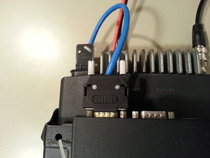
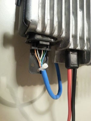
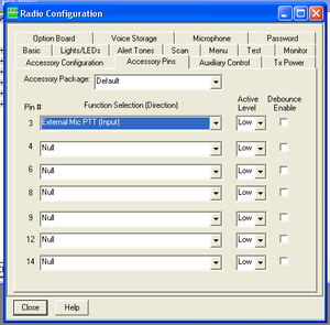
Based on my notebook, the interface cable between my OT3m and the CDM750 is as follows:
      OT3m pin --- CDM750 pin (purpose)
             1 --- 5 (Audio Out)
             3 --- 3 (PTT)
             5 --- 11 (Audio In)
             6 --- 7 (GND)
             7 --- 13 (PWR IN)
You want to be really careful when you use the modulator pin (5) on the Moto 16 pin, because it won't keep you from grossly over-deviating and exceeding the channel bandwidth. This is when having a friend with a service monitor pays dividends.
This cable is also pulling power out of the radio for the OT3m and GPS puck, so no need to hook anything up to the barrel jack!
I used the kludge of shorting pins 4 and 10 of the CDM accessory plug to make it auto-power on.
I bought the Moto 16 pin shell + contacts from Digikey (let me know if you want me to dig up the part numbers) but there's also kits for them available on eBay.
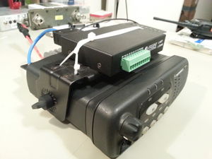
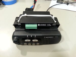
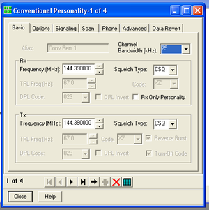
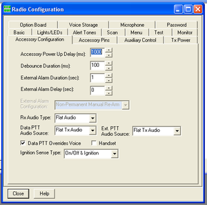
Here's some pictures of my tracker and screenshots of CPS:
Older Moto Info
The Motorola 16 pin accessory connector can provide all of the signals necessary to interface to an OT product, including providing enough current to power the unit.
Some Motorola radios have other pins as programmable options beyond what this diagram shows. All radios I have run across so far have been able to be programmed to match the pin out provided. I have successfully interfaced to Radius SM-50, Radius SM-120, and Radius M1225 units. I have provided a COR signal connection, although I run the RX audio output on pin 11 in an unsquelched mode, providing live audio 100% of the time, and set the OT2 for software carrier detect.
