Difference between revisions of "T3-301"
(→System Description) |
(→System Description) |
||
| Line 12: | Line 12: | ||
*Note that for the T3-301 the SETPOWER command range is from 1-5 (corresponding to approximately 1-5 watts RF power output). (The T2-301 used a 1-99 scale for power.) | *Note that for the T3-301 the SETPOWER command range is from 1-5 (corresponding to approximately 1-5 watts RF power output). (The T2-301 used a 1-99 scale for power.) | ||
| + | |||
| + | === Pin Description === | ||
{| class="wikitable" border=1 | {| class="wikitable" border=1 | ||
Revision as of 10:14, 1 April 2016
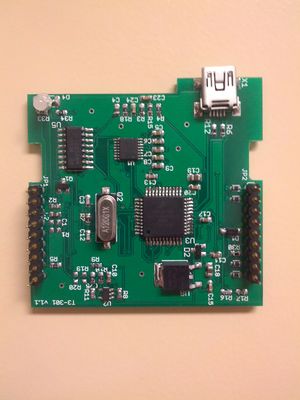
The T3-301 is a Tracker3 board integrated with a Friendcom FC-301 D transceiver. It is almost identical in setup and pinouts as the T2-301.
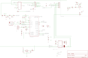
The main Tracker3 page covers information relevant to all Tracker3 variants. This page contains only information specific to the T3-301 model.
Product Concept
The goal of this product is to create an integrated Tracker3 and transceiver package for simple and professional installations and integration with (for example) a Garmin FMI capable device. It can also be used with just a GPS and power supply to serve as an APRS tracker and digipeater functionalities.
System Description
The Tracker3 board replaces the "interphase connection board" inside the FC-301/D radio and intercepts all the data and I/O lines going to the DB9 connector effectively hijacking the system's audio and TX/RX control. (NOTE: This means that the T3-301 and FC-301/D have different pinouts and cannot be interchanged.) Internally, the Tracker3 takes all the DB9 pins except for power and ground (which are hardwired in the FC-301/D) and uses them as inputs to the Tracker3. The normal outputs from the Tracker3 are then sent out to the DB9 connector to provide the usual PortA and PortB serial, IRQ, and 1-wire interfaces.
- Note that for the T3-301 the SETPOWER command range is from 1-5 (corresponding to approximately 1-5 watts RF power output). (The T2-301 used a 1-99 scale for power.)
Pin Description
| Pin | Function |
|---|---|
| 1 | Port B data in (to tracker) |
| 2 | Port A data out (from tracker)s |
| 3 | +5v power out |
| 4 | Ground |
| 5 | Power in (9 to 15v DC, 1.5 amps) |
| 6 | IRQ / Counter input |
| 7 | 1-Wire data bus |
| 8 | Port A data in (to tracker) |
| 9 | Port B data out (from tracker) |
System Specifications
Measurements taken at 13.8V system voltage of the T3-301 tracker, FC-301/D radio, and ADS-GM1 GPS. Actual Measured Values (Oct 27, 2013, AI6MS using HP8920B Test Set)
- DC Standby Current: 150 mA
- DC Receive Current: 160 mA
- DC Transmit Current (Max Power): 1.2 A
- RF Power Out (Max Power): 5.6 W
- RF Frequency Error: +0.011 kHz
- AF High Tone Frequency: 2201.1 Hz
- AF Low Tone Frequency: 1201.2 Hz

