Difference between revisions of "LCD Interfacing"
m (→Connecting an LCD to the OT2m) |
(No difference)
|
Latest revision as of 06:02, 7 October 2009
Some Tracker2 and OpenTracker+ models support connection of an HD44780-compatible liquid crystal display. Connection details for specific models are provided here.
Display Contents
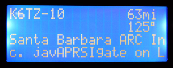
Currently the Tracker2 displays an information screen for each received position, showing the callsign, distance, direction, and comment text.
Connecting an LCD to the OT2m
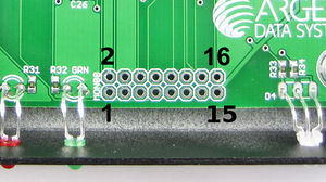
The Tracker2 is configured for use with a 20-character by 4 line display. The display connects to the MON08 programming header at the front of the OT2m PCB. LCD pinouts vary, but for the most common type the connections are as follows:
| MON08 | LCD | Function |
|---|---|---|
| 1 | 4 | RS |
| 2 | 1 and 5 | Ground and R/W |
| 3 | 6 | E |
| 8 | 14 | Data7 |
| 10 | 11 | Data4 |
| 12 | 13 | Data6 |
| 14 | 12 | Data5 |
| 15 | 2 | +5v |
Assuming the display requires a positive voltage for contrast adjustment, you will need to install a resistor between pins 1 and 3 of the LCD. A few hundred ohms is typical, but this depends on the display used and the viewing angle.
No configuration is necessary. The standard Tracker2 firmware will begin using the display automatically.
This is an example of a wiring harness with the regular controls and the addition of contrast and backlight control.
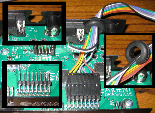
If the LCD harness needs to be removed, then the following example may serve as an example.
Upper left inset, the case was notched. Lower left inset, a connector was added to the PCB. Right inset, grommet was split. Overall photo depicts connector and cable passing through the back. Note: Ignore black and white wire. They were extras. The split in the grommet is on the bottom, away from the opening in the case.


